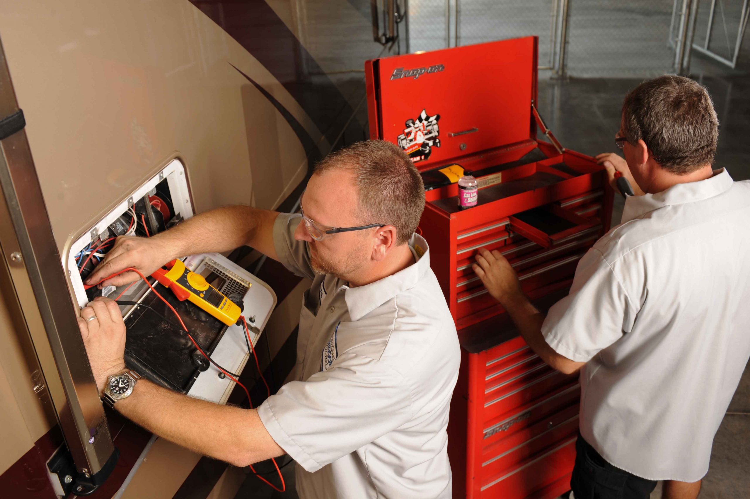
Last month our tutorial covered batteries, generators, transfer switches and inverters. This month is part three, our final installment of this three part series on RV electrical systems. We’ll get into solar power, surge protection and energy management systems.
Low Voltage Circuits:
Motorhomes are meant to be used when 120 volt shore power is not always available. It would be a real pain if every time you walked into your motorhome you had to fumble around in the dark to start the generator so that you could turn some lights on, which is why RVs have 12 volt battery powered electrical systems as well as 120 volt AC electrical systems. The 12 volt system provides power to operate the interior lights and the many other 12 volt electric systems within the coach, such as fans, water pumps and furnaces. These systems will be connected to the coach battery bank via a 12 volt fuse panel that is located somewhere inside the coach. A converter or inverter/charger will also be connected so that these batteries can be recharged from shore power or when running the generator.
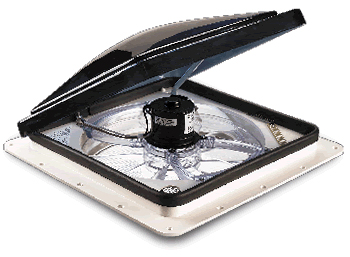
Powered vent fans are commonly used in most RVs.
Powered roof vent fans, such as the one pictured above, are found in most every RV. In addition, you’ll undoubtedly find that you have a tank monitoring system to check the levels of your fresh water, propane tank, and holding tanks. This information may be displayed on a small remote panel or incorporated into a networked touch screen control panel. Your refrigerator and hot water heater are designed to run on either 120 volt AC current or propane. But, you will need 12 volt power to operate the igniter and the control circuitry for any propane fired refrigerator. Even the light bulb inside that fridge is powered by 12 volt power. Basement compartment lighting and power awnings are other examples as is the power steps that allow you to enter your motorhome.
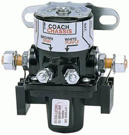
A typical battery disconnect solenoid.
If you were to leave your motorhome parked for a while and shore power was not available, the various parasitic loads on the 12 volt circuits would eventually drain the batteries. RVs have a battery disconnect switch, which is generally located close to the entrance door. This switch controls a battery disconnect solenoid. This solenoid is a latching solenoid which means you send it power to move it but you do not have to continue feeding it power in order to hold it in that position. This makes it perfect for an RV application because the solenoid won’t consume any battery power when parked. Pressing the rocker switch in one direction will shuttle the solenoid to the open position while pressing the rocker switch in the opposite direction will send the shuttle in the other direction and close the circuit. This allows for an easy way to shut down the 12 volt power to the coach while you are away. If you are plugged into shore power, this is not necessary. Keep in mind that not everything will be disconnected when the solenoid is in the off position. Some loads, such as inverters, keyless entry systems and propane leak detectors bypass the solenoid and will remain active.
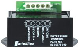
Typical water pump controller
Your fresh water tank needs a water pump in order to pump water from the tank to the faucets when you are not connected to a campground’s pressurized water supply. This pump generally has a number of switches located by the various plumbing fixtures so that you don’t have to run to a central panel to turn on the water pump. In order to allow all of these switches to control one water pump a water pump controller is used. A water pump controller is another latching relay that allows a number of switches to send a small trigger signal to turn the controller’s relay on or off. The relay will then take a larger 15 amp power feed and send it to the water pump to turn it on. The controller also sends out an “on” signal to all of the indicator lights that are located by the switches throughout the coach so that the user knows whether the water pump is on or off.
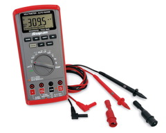
A multimeter is an indispensable tool for every RV owner
Sometimes these systems can fail, not that this will come as a shock to anyone. When electrical systems fail it’s time to do some testing to see where the failure is. A voltmeter is a huge help in this area although a test light can also be used to test low voltage circuits. Personally, if you are a motorhome owner you should have a multi-meter of some sort. It’s invaluable for checking high voltage circuits, campground pedestals, low voltage circuits, and continuity.
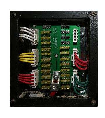
Fuse panels hold fuses for all 12-volt systems.
The first thing to do is to check for blown fuses. Sometimes you can do this by removing the fuse and holding it up to the light to determine if the fusible link is blown. Sometimes it’s not so easy to see. The way many of these fuse panels are labeled, or more accurately, “not” labeled, you may have trouble figuring out which fuse does what. The common ATO fuses are blade type fuses with a plastic housing. There are bare spots on the end of the housing that can be used to test for voltage. If you have power going into the fuse, but not out of it, you’ll know you have a bad fuse. Another method is to use the ohms setting on a multimeter. Remove the fuse and check for continuity with the meter. If no continuity, the fuse is bad. If you have a critical circuit you can also replace those fuses with ATO style circuit breakers that plug right into place. There are also fuses with LED pilot lights that will illuminate if the fuse is blown. So, you have lots of options when it comes to fuses.
If it’s not a fuse, then you need to look a little deeper. If the fuse does have power leaving it, test for voltage at the device that isn’t working. If you have power coming into the device it’s either a bad device (light bulb, fan motor, water pump, etc.) or else you do not have a complete circuit. In that case I’d check for a bad ground because an open ground won’t give you the complete circuit back to the battery. If you do not have power at the device there is an open circuit between the fuse and the device. The first place to look would be at the switch. Test to see if there is power coming into the switch and power exiting the switch. If the power is getting to the switch but not leaving it, it’s time to replace the switch.
| Wire Gauge (AWG) | Wire Diameter, in Inches | Current Capacity, in Amps |
|---|---|---|
| 0000 | .4600 | 600 |
| 000 | .4096 | 500 |
| 00 | .3648 | 400 |
| 0 | .3249 | 320 |
| 1 | .2893 | 250 |
| 2 | .2576 | 200 |
| 4 | .2043 | 125 |
| 5 | .1819 | 100 |
| 6 | .1620 | 65-80 |
| 8 | .1285 | 40-50 |
| 10 | .1019 | 30-33 |
| 12 | .0808 | 20-23 |
| 14 | .0641 | 15-17 |
| 16 | .0508 | 7.5-10 |
| 18 | .0403 | 5 |
| 20 | .0320 | 3.3 |
| 24 | .0201 | 1.3 |
| 28 | .0126 | 0.5 |
This chart shows the current capacity for various wire gauge sizes.
Above is a wire gauge capacity chart. Wires are just like water pipes in that you can only pump so much stuff through a given size pipe without losing pressure. If you try to send too many amps through too small of a wire the voltage will drop, the wire will get hot, your device won’t run properly, and you’ll probably blow the fuse for that circuit. The above chart serves will give you a good idea as to what wire gauge you will need to use if you want to add an accessory to your RV. For example, if you want to add a small fan to your RV that has a motor rated at a 4 amp draw you will need to go with a #18. The 20 gauge wire is only rated for 3.3 amps while the #18 can safely handle up to 5 amps so you always round up. If you want to install a water pump that pulls 20 amps, you’ll need to use a #12 wire. If you want to add an inverter and its DC battery draw is 400 amps you will need a #00 wire. Keep in mind that you can always go to a larger wire gauge without any bad results but you can never go smaller. Also, the length of wire will also affect its ability to carry current. If you are running long runs of wire you may need to increase the wire gauge to allow for the extra resistance incurred by the extra lengths. In this case, use the above wire gauge chart conservatively when choosing which wire gauge to use. Going larger is always a safe bet.
Inverters:
As we learned earlier, inverters do just the opposite of converters because they create 120 volt AC power from 12 volt DC battery power. In actuality they don’t “create” the power, they transform it. An inverter uses electronic signal processing circuitry and transformers to bump the 12 volts up to 120 volts and change the DC current into AC current. The electronic circuitry creates the proper frequency and voltage levels that make up the waveform of the output current so while the inverter doesn’t really create power, it takes existing power and molds it into a different output. In the process of doing so there will be a slight loss of between 6 and 15% so just because you are inputting 2,000 watts of battery power doesn’t mean you’ll be getting the full 2,000 watts as output.
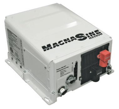
A Magnum true sine wave inverter/charger.
Inverters are available in many sizes. Inverters can be as small as 175 watts. These units can plug into a 12 volt power socket and be used to power a small power tool. Larger inverters can be direct connected to a battery source and mounted in an RV’s cabinet to power TVs or other entertainment equipment. Some of these inverters can run 1,000 watts, or even 1,800 watts in size. The second style is the inverter/charger. These units are larger and designed to handle multiple circuits and typically range from 2,000 watts to 3,000 watts in size. They also provide battery charging capability so when an inverter/charger is used the converter is eliminated because it’s no longer needed.
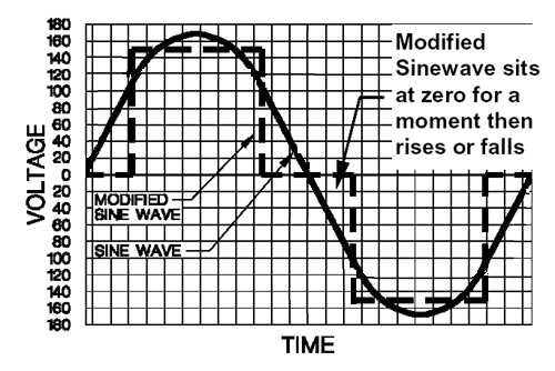
Chart showing difference between true sine wave and modified sine wave
Inverters may output one of two waveforms. The waveform that is output by a generator set is a true sine wave. The power put out by your public utility is also true sine wave because it too is created in a generator, even though it’s a very large one. The voltage will rise and fall like a large S-curve as the field passes by the magnets in the generator. This creates a wave where the peak voltage appears for an instant, then falls back down to zero. However, peak voltage is meaningless. Your equipment is designed to run on 120 volts RMS (Root Mean Square) voltage, which is the voltage level at a given width of the wave. Voltmeters will also read RMS voltage so there are no calculations or anything complex to have to worry about
Inverters do not have rotating parts and magnets. Instead, they create the desired waveform and frequency electronically. The earliest inverters were known as modified sine wave inverters. The waveform created by these inverters took a straight vertical leap to a given level, then traveled in a straight horizontal line for a given time, then fell instantly back to zero volts and rested for a while before repeating this cycle over and over again. Unfortunately, this power can create issues with sensitive electronics equipment and electric motors because it is not a true sine wave. A standard voltmeter will read this as a much higher voltage, probably around 150 volts rather than 120 volts. It takes a special voltmeter to take modified sine wave readings. The biggest problem is that electric motors and integrated circuits get messed up by this as well. But, at the time there wasn’t that much high tech stuff on the market and modified sine wave inverters were an affordable alternative.
As electrical components became more complex, so did the need for inverters with a cleaner waveform. The advent of the true sine wave inverter gave us that ability. Fortunately, as electronics improved, so did the ability to make cost effective true sine wave inverters. A true sine wave inverter perfectly matches utility power and there are no longer any limits to what can safely run on it. The graph above shows the difference between the two sine waves. If you are running simple things, such as lighting, you won’t really have an issue with modified sine wave. Modified sine wave inverters will power toasters, lights, microwaves, any electrical heating element, as well as most motor loads such as refrigerators, vacuums, etc.
Electronics do not fare as well on a modified sine wave. Digital clocks will not keep accurate time. Many small battery chargers, such as used on cordless power tools will not function correctly. And any electronic device is subject to failure. The biggest issue is that all major appliances are now becoming heavily interfaced with electronics. While your refrigerator’s compressor motor may run fine on modified sine wave, the electronic control panel in the door that controls the water dispenser and ice maker may not like it and will fail. Microwaves ovens will function but the electronic control panel may not hold up that long. In fact, you will most likely hear the difference between shore power, which is true sine wave, and when on the modified sine wave inverter as the microwave labors when on the inverter.
Laptop computers will run fine because the inverter is merely powering a battery charger. The battery itself acts as a buffer and runs the laptop on DC power, even when plugged into the AC adaptor. Desktop computers are not in the same category though and you will probably damage them quite quickly. Modified sine wave inverters will also generate RF noise in the line so you will have issues if you try to power a ham radio with one. Motor speed controllers using triacs won’t work properly either. If there is a “wall wart” power supply box plugged into the wall you’ll be fine though. Inkjet printer models can be either way on this so check first. Generally, if you see the current transformer on the power supply, you’ll be fine.
Inverter Operation
A simple inverter isn’t that hard to figure out. It connects to a battery power source and you plug your AC load into the receptacle. You turn it on and it works. Larger inverter/chargers are a bit more complex. An inverter/charger also has a 12 volt DC battery input and a 120 volt AC power output. These units are larger so they are generally hard-wired into the coach’s electrical systems. The inverter also has a 120 volt AC power input connected to it as well. Inside the inverter is an automatic transfer switch to handle switching of the inverter’s AC output from between the inverter created power and the 120 volt bypass power. Whenever you are plugged into shore power or the generator is running, there will be 120 volt power present at the inverter’s bypass power inputs. The inverter will simply pass that power through to the inverter’s output. This is referred to as pass-through or bypass power. Whenever 120 volt AC power is not present at the inverter’s inputs the inverter will create (“invert”, actually) AC power from the 12 volt DC batteries and the transfer switch will flip over to the inverter’s own power output to feed the desired devices. Because of this it is not necessary to turn the inverter off and on because the transfer switch will handle the changeover in power sources automatically
Whenever pass-through power is present the inverter/charger also acts as a battery charger. In addition to passing through the AC input current, some of that power is drawn off to operate the battery charger mode of the inverter/charger. Instead of drawing power from the batteries to make 120 volt AC output, it now uses the available AC input power to help put some power back into the batteries by recharging them. Modern inverter/chargers utilize 3 stage battery charging algorithms. Initially it will output up to 14.8 volts as needed in a bulk charge mode. As the batteries near completion the charge will taper off into an absorption mode. Finally, the charger settles into a float mode where the charge voltage will not exceed 13.2 volts. This is a maintenance mode designed to hold the battery at its fully charged state while at rest. Inverter/chargers do have on/off buttons to disable either or both functions but they are not normally needed because the inverter/charger will automatically switch back and forth as needed. However, when the coach is stored it’s not enough to switch off your output circuits. An inverter will have a slight idle current even while not in use if it is allowed to be powered up. When storing your coach without shore power be sure to switch off your inverter and charger at the inverter itself to eliminate the idle current from slowly draining your batteries.
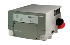
A Xantrex 2,000-watt true sine wave inverter/charger
Inverter Installation
If your RV doesn’t have an inverter, but you would like to install one, be sure to download a copy of the manufacturer’s installation manual from their website and read it first before buying your inverter. Inverters do need the proper environment. True sine wave inverters can create a fair amount of heat. If you place them in a large basement pass-through storage area you’ll be fine but if you place them in a small enclosed compartment they will overheat. In that case you’ll need to provide some intake air as well as a place to exhaust the heat, preferably with a fan. The next consideration is providing battery power to the inverter. Larger inverters need lots of battery amps in order to provide power. This means large diameter battery cables are required. You also need to keep the length of these cables short so you’ll want to locate the inverter close to the batteries rather than run huge cables a long distance. Again, refer to the manufacturer’s manuals for specific details.
You’ll also need to fish a network cable from the inverter to a handy location where you will mount the remote display panel that controls the inverter. You’ll also need to run another cable as you connect to the battery temperature sensor that needs to be mounted on the batteries. Lastly, you’ll need to run AC wiring from your main breaker panel to power the inverter and then run the inverter’s AC output to a sub-panel so that you can feed all of the desired circuits that you want the inverter to handle. As the inverter size increases, so do the difficulty levels of all the above tasks so plan carefully before spending your money. You may find it best to have the installation done by professionals if this kind of work is out of your wheelhouse.
Automatic Generator Starting:
Automatic Generator Start (AGS) systems do just what you think they might do – they start your generator set automatically, even if you are not near the coach. These systems vary in complexity and design. Some systems are standalone systems and are simply a module that connects to your generator set to start it if your batteries get low. Some systems, such as the Onan EC-30, are an all-in-one system that builds the circuitry into its remote display and control panel. This system design also includes a thermostat interface so that it can start your generator in response to a request for cooling from the air conditioner’s thermostat. Other systems, such as the Xantrex and Magnum AGS modules, are designed to network with an inverter and use the same remote display panel as the inverter to control both the inverter and AGS module via menu driven software. So there are a number of options and choices available when selecting an AGS module.
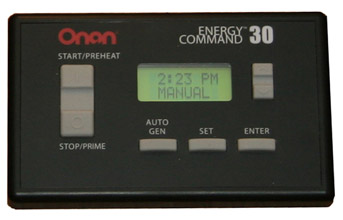
The Onan EC-30 Automatic Generator Start module.
Selecting an AGS System
The first thing to do is determine just why you want an AGS system in the first place. If you are only going to run your generator to power air conditioning when driving you probably don’t need one. If you will be dry camping quite often you will need to run your generator every now and then to recharge your batteries. If your batteries drop below a given voltage your AGS can start the generator set for you automatically while you are off sightseeing so that you don’t return to a dead coach. This is the basic feature of any AGS system. You can also recharge your batteries while you sleep if they drop down during the night without having to worry about setting your alarm clock. Many campgrounds do have a quiet time posted where no generators may be run during the evening but more advanced AGS models include a quiet time setting that can be set. In that case the AGS module will not start your generator during those quiet time hours and will wait until morning to auto-start. Some models, like the Onan EC-30, include predictive scheduling. The AGS will monitor your battery voltage level and if it determines that it will need to recharge them during quiet time, it will start the generator earlier and then shut off so that they will be recharged when your quiet time begins.
The next level includes a thermostat interface. Your AGS system will be connected to your air conditioning system’s thermostat. If a request for cooling occurs, the AGS will start your generator and power the air conditioning system to prevent your coach from overheating. Some systems also include a shore power connection so that the AGS will only start the generator if there is no shore power present. This is a great feature for RV owners who have pets and normally camp in full service campgrounds. The shore power will power your coach’s air conditioners to keep your pets from overheating. But, what happens if the shore power was to go out or the pedestal breaker tripped while you were away from the coach? Your air conditioners would stop working and you might be returning to a coach with pets that suffered heat stroke.
If you have an AGS that does not have a shore power sense, but does have a thermostat connection, you’ll find that the generator will start up every time the thermostat calls for cooling – even when the shore power is functioning. This is not desirable so you will have to install a relay that is fired by the shore power side of the transfer switch and then intercept the low voltage wires that connect the thermostat to the AGS module. This will break the circuit whenever shore power is present so that the AGS never sees the input signal from the thermostat. When the shore power fails the relay will allow that connection to take place. With an AGS that has shore power sense you won’t have to worry about that. All of the logic is handled within the AGS electronics and it won’t start the generator if shore power is present. If shore power fails and cooling is desired it’ll start the generator and your pets will be safe.
If you have a Silverleaf or Firefly networked whole coach system that controls most coach functions via a multiplexed network you most likely have a bridge, which is a device that bridges the communication with the inverter/charger and the Vegatouch control system. This allows complete control of the generator and AGS module via the master control touch screen in the coach.
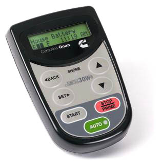
The Onan EC-30W AGS unit uses a wireless controller
Installing an AGS module requires a bit of work. You need to run wiring connections to the transfer switch mounted transformer as well as the batteries, generator start-stop switch, remote control panel and HVAC thermostat. Fishing all of those wires can be tedious and sometimes difficult. Wireless units will save you some time by allowing those connections to be performed under the floor in the chassis area, using wireless operation to the remote display panel in the RV. The Onan EC30W is the premier wireless system. The remote unit communicates wirelessly to the main harness and even contains a temperature sensor so that you don’t have to tap into the existing HVAC thermostat. You do have to be careful of where you place the remote though. If you set it in a hot spot it’ll be triggering the generator prematurely. You also run the risk of communications failure, which can happen with any wireless electronic device, particularly when you consider that the signal needs to pass through the motorhome’s steel firewall.
Solar Power:
Solar panels are widely misunderstood. The most common question posed is “How many solar panels do I need to run my RV?” But, the fact of the matter is that solar panels don’t run anything. It’s your batteries that will provide enough amp-hrs to power your electrical devices. Solar panels don’t output enough amp-hrs to run a device but they will continue to provide that slow and steady output over a fairly long time frame so in effect, solar panels are strictly battery chargers. Your electrical devices will draw amps from your batteries but solar panels will put some amps back into those batteries. Unless you have a massive solar panel array or are a real miser with your power consumption, you’ll never be able to keep your batteries from running down. Eventually you will need to run your generator to recharge those batteries and bring them up to a full charge. However, solar panels can add enough extra amps to extend the timeframe between generator runs so that it occurs at a time that’s more convenient for you.
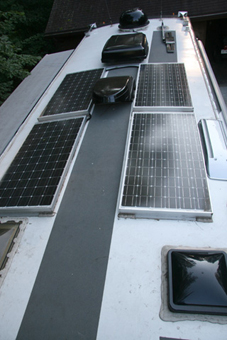
A solar panel array featuring four 120-watt panels on a 40’ coach
One of the biggest limitations of solar panels is that you need enough of them to make a difference. If you think that slapping a 50 watt panel on the roof is going to do something, then you are wasting your money. Unfortunately, panels take up some room and not every RV roof has an overabundance of that. The image above shows an array of four 120 watt panels on a 40′ coach. It was possible to place two on each side and still be able to walk down the center of the roof for service access on the gray non-skid surface. One of the biggest limitations of solar panels is that you need enough of them to make a difference. If you think that slapping a 50 watt panel on the roof is going to do something, then you are wasting your money. Unfortunately, panels take up some room and not every RV roof has an overabundance of that. The image above on the left shows an array of four 120 watt panels on a 40′ coach. It was possible to place two on each side and still be able to walk down the center of the roof for service access on the gray non-skid surface.
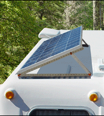
Solar panels with tilt mounts align the panel to the sun for better performance
Solar panels create the most power when they are getting direct sunlight and lots of it. They can be ordered with flat mounts or tilt-up mounts. Tilt up mounts have the advantage of being able to be aimed at a southern exposure so that the solar panel can receive more light throughout the day. You do have to park the RV so that the panels are facing south though and that’s not always an option. Also, if you forget to put them down and lock them before driving away you’ll be buying new panels and patching some holes in the roof where they used to be mounted to. Overall, flat panels are the safe bet for a motorhome. The benefits of an adjustable mount just aren’t that much that it pays to put up with the hassles they bring unless you are staying in one place for a long time.
Solar panels vary in output but it’s proportional to their size. You won’t find a panel that has significantly higher output than another in the same physical size. The biggest difference in panels is their ability to produce power under less than optimal conditions. Unfortunately, there is no rating method or specs that will tell you this so you’ll have to rely on information from other owners or a sales rep that you can trust. Some panels will put out their maximum rated output when it’s nice and bright but fall off sharply when the light is dimmer later in the day, early in the morning, or when it’s overcast. Some panels continue to produce respectable light output under less than optimal conditions. Those are the ones you want to have because it’s all about the total amp-hrs output during the day, not just what’s happening at high noon.
You’ll need to determine just how many amp-hrs you’ll be using during a 24 hour period. Take the wattage of any 12 volt items, such as lights, fans and blower motors, and divide by 12 to find the amps. Then multiply that number times the numbers or hours (or portion of an hour) that each item will be run during that day. Make a note of that number. Then do the same for all of your 120 volt loads except divide those wattage amounts by 10 instead of 12 to find out how many 12 volt amps will be needed to feed the inverter. This will allow for a 20% inverter efficiency loss, which is more than adequate for planning purposes. Add everything up and that’ll tell you how many amp-hrs you’ll need to run everything during a 24 hour period. Go look at your battery bank size. A typical four battery bank of 6 volt golf cart style batteries should be around 440 amp-hrs in size at 12 volts. You don’t want to run these batteries below approximately 50% charge level so you should limit their use to 220 amp-hrs before recharging them. If your above calculations show that you are consuming more than that, you won’t make it through the day. Calculate the difference between what you need and what you have and that’s your shortage. If you can install solar panels to exactly supplement that amount you’ll be able to make it 24 hours before recharging via the generator.
If you are an avid boondocker chances are you’ve figured out ways to minimize your power consumption. By doing the above math you may find that it’s possible to camp for a number of days before needing to run the generator. Solar panels can help extend that as well. Remember that we said earlier that solar panels don’t run anything. What they do is provide “free” amp-hrs of battery charging power that can help extend your recharge times to where it is more convenient for you. One other option is to just add more batteries. Extra batteries will cost you far less than solar panels so if all you are looking for is a few extra hours between charge cycles I’d look at adding batteries. If you do decide that solar panels are a good fit for your RV style then you still may want to add additional batteries. If you use AGM batteries rather than flooded batteries you’ll also get more runtime. This was discussed earlier in the Batteries chapter. Another way to maximize your solar panel output is with a good charge controller.
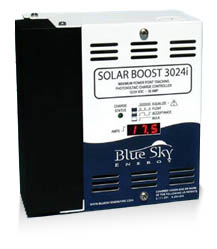
A 30-amp MPPT solar charge controller
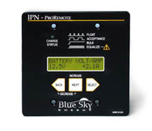
A smaller Blue Sky charge controller
Charge controllers connect between your solar panels and your batteries. They vary greatly in price and capabilities. The simplest charge controller acts as a diode, or check valve, to prevent dark current. Without this check valve your battery current would drain into the solar panel at night. The charge controller is a one way valve that prevents dark current from happening so that your batteries can retain their charge. Whenever the solar panel output voltage falls below the battery voltage the charge controller opens the circuit between the two. The second function that charge controllers do is to provide voltage regulation. In bright sunlight a solar panel may produce 18 volts or more. The battery doesn’t need or want that kind of voltage so the charge controller regulates it to a safe level. Simple charge controllers generally have a low wattage rating, usually 15 to 20 amps, and are mounted into a hole cut into the wall. There’s nothing very fancy about them and they are inexpensive. The next step up is a charge controller that features 3 stage charging. Just like our inverter/chargers and converters there will be a bulk charge, absorption charge, and a float charge. These can be wall mounted or larger units located in a basement compartment. They could be as low as 20 amp or much higher. The larger sizes, such as 30 and 50 amp usually offer an optional remote control panel that can be mounted inside the RV to monitor operation. One real benefit is in getting a charge controller with MPPT (Maximum Power Point Tracking) technology.
MPPT technology makes a huge difference in solar panel output and it really doesn’t pay to go with solar without an MPPT controller. Remember our earlier discussion about amps, volts, and watts? Wattage is true power. Amps times volts equals watts. Solar panels have a fairly high maximum output voltage, which drops as the light intensity fades. A 120 watt panel that’s outputting 16 volts will give you 7.5 amps of current. Your battery doesn’t really care what voltage is coming in. As long as the incoming voltage is higher than the battery voltage it’ll take a charge. All it really wants is to see some amps. If we were to modify that 120 watts of power and drop the voltage down to 12 volts we would have 10 amps of battery charging current. A simple non-MPPT controller merely clips off the excessive voltage, wasting valuable amps in the process. But, an MPPT Controller will trade volts for amps and you’ll get some free current that you wouldn’t otherwise have gotten. On the average an MPPT controller will give you 30% more charging power over a non-MPPT controller. It’s like getting a free extra solar panel in the bargain.
One other feature is voltage transformation. Solar panels can be connected in series or parallel. If they are in arranged in parallel the voltage remains the same but the amperage is multiplied by the number of panels. For instance, a 120 watt panel should theoretically put out 10 amps each at 12 volts. A bank of four of the connected in parallel would yield 40 amps at 12 volts, which is equivalent to 480 watts. If these panels were connected in series they would produce 10 amps at 48 volts, which is also 480 watts. The problem is that our batteries are 12 volts, not 48 volts. But if we had a charge controller that was capable of taking a higher voltage input and transforming it to a lower voltage output it would work. One such charge controller that will do that is the Outback FLEXmax MPPT Charge Controller. It’s available in 60 amp or 80 amp versions and can take an input level as high as 60 volts and output it as 12 volts. The benefits to this are several.
First of all, wire gauge is relative to how many amps it will carry. As we saw earlier in our wire gauge charts, 40 amps requires a larger #8 wire while 10 amps can get by with a much smaller #16 wire. This can make it much easier, and less expensive, to install. Secondly, when the sun begins to set low on the horizon the lighting level is diminished. A 12 volt array may only be capable of 10 volts at that time so you won’t be getting any more power from those solar panels. But, if it was a 48 volt array you would still have 40 volts left over for the charge controller to convert to 12 volts and feed the battery bank. This will give you even more amp-hrs per day. Voltage step-down controllers such as the Outback isn’t the cheapest controller available but it appears to be the best at maximizing your solar panel array’s output.
Energy Management
Energy Management is simple – you just need to make sure that you don’t use any more power than is available. Battery power is finite. Eventually it’ll run out. By minimizing how many lights are on and the time they are on, battery life can be extended. Eventually you’ll need to recharge them, either by driving the coach or by running the generator. Adding extra batteries can extend that runtime as can the addition of solar panels. If you are plugged into shore power this isn’t an issue because your converter or inverter/charger will keep them charged while you use them.
AC power is a bit different. Unlike battery power, there is no reserve to draw from. You are limited to the total current capacity of your shore power pedestal or your generator’s capacity. Generators are generally sized for that particular coach so you should be able to run whatever loads you need to operate without exceeding the generator’s capacity. Of course there are exceptions where an undersized generator was specified in that particular coach rather than choosing the optional generator but those are the exception, not the rule.
Shore power pedestals vary in size. If you are running a small 20 amp cord to your RV from someone’s home you’ll be very limited as to what you can run. Battery chargers vary in current draw as to how many battery amps they are outputting. A battery charger that is outputting a full 100 amp bulk charge at 12 volts will be drawing 10 amps of 120 volt AC power. That can take up one half of your 20 amp circuit, which doesn’t leave a whole lot left. Many inverter/chargers have a setting on the remote control panel to define the shore power service. If you define the shore power at a lower level, say 20 amps, then it will limit the 120 volt power that they battery charger uses so that you can have more left to run other 120 volt items. You will need to manually set this once you are plugged into a smaller shore power pedestal.
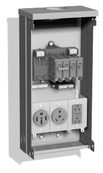
A typical RV pedestal with multiple 50-30-20-amp receptacles
In the above image we can see three receptacles. This is a typical 50 amp pedestal which features a 50 amp, 30 amp, and 20 amp outlets. This pedestal allows virtually any type of RV to be serviced with power. The 50 amp outlet is a 120/240 volt split-phase outlet, capable of 12,000 watts of total power. If you have an RV with 50 amp service you should have no problems powering your RV’s electrical appliances when plugged into a 50 amp outlet. Older pedestals may only be configured with a 30 amp outlet however. This is a single pole 120 volt feed, capable of 3,600 watts of total power. You can adapt your 50 amp coach to this 30 amp outlet via a dogbone adaptor but you will be severely limited in just how much you can run in your RV. If the battery charger is pulling 5 amps and your two air conditioners are pulling 12 amps each you’ll be drawing a total of 29 amps. All it takes is for the electric water heater element to kick in or someone turning on the microwave and you’ll trip the pedestal breaker and you’ll be making a trip out to the pedestal to reset it, which of course always happens when it’s raining.
Manual energy management entails turning off some loads so that you can turn on others. If you really need to get hot water it would be best to use the propane burner instead of electric if it’s hot out. If you need to use the microwave for a bit then you’ll have to shut down one of the air conditioners so that amperage can be used by the microwave temporarily. Eventually this gets to be tiring and you’ll either find places to stay at that only have a 50 amp service or you’ll wish you had an automatic energy system.
Automatic Energy Management Systems
An Energy Management System (EMS) automatically performs the circuit switching procedures for you. Do not confuse a true EMS system with surge protection. Some name brand surge protectors use the term EMS in their models and descriptions. In a way, this is true because they do more than stop surges. They also protect from low or high voltage but they are still part of the surge protectors category. True EMS systems do not consider voltage levels. They only monitor the amperage draw and perform shedding of various circuits to keep the total power consumption beneath the pedestal breaker rating.
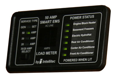
The remote display panel from the Intellitec Energy Management System
The most popular Energy Management System of years back was made by Intellitec. The Intellitec system consists of a custom breaker panel which has four 120 volt relays and two low voltage relays. These relays are controlled by a proprietary electronic module that turns these relays on and off as needed. The board senses the power that is coming into the breaker panel. If it sees 240 volts across L1 and L2 it knows that it is a 50 amp feed and it performs no energy management tasks. If it sees 12 volts at the terminal that is connected to the generator’s hour meter it knows that the generator is running. In this case it will display the amperage on the remote display panel but will not perform any load shedding tasks. If the generator run signal is not present and 240 volts is not present it will know that you are on a 120 volt single pole shore power feed. It will default to a 30 amp setting but you can change it to 20 amps if you need to by pushing that button on the remote display panel. In this mode it will display the amps being used and shed any circuits that need to be shed in order to remain underneath the 30 amp (or 20 amp if selected) limit of the pedestal breaker. The loads are shed according to a pre-determined load shedding order, whereby the least critical circuits are shed first. The biggest drawback to this system is that the breaker panel is quite large at over 20” in width, which makes it difficult, if not impossible, to install when retrofitting a coach without an EMS. This system has since been discontinued and RV manufacturers are now going with a newer, more technologically advanced unit by Precision Circuits, Inc.
Let’s assume that you want to run two air conditioners (at 12 amps each), the electric water heater (at 10 amps), and your battery charger (4 amps in float mode). That’s a total of 38 amps, which won’t work on a 30 amp service. We’ve already switched the refrigerator over to propane so that’s out of the equation. The EMS will shed the first available load, which is the water heater so that everything else can run. You’ll then be drawing 28 amps. When the thermostat kicks out one air conditioner the load will be reduced to 16 amps so power to the hot water heater will now be restored and the new load will be 26 amps. If someone turns on the microwave and needs another 11 amps, the total draw would be 37 amps so the EMS will shed the next item on the list so now the water heater and one air conditioner will be shed. When the microwave is finished the next priority level circuit will be restored, which in this case is the air conditioner. By doing this the EMS prevents the pedestal breaker from tripping by limiting the total current.
A more recent entry into the energy management field is an EMS by Precision Circuits, Inc. This unit operates in similar fashion to the Intellitec system except it takes it one step farther. It actually interfaces with the inverter and will trigger the inverter so that it powers its output circuits rather than passing through shore power. This way when someone operates the microwave the inverter will power it rather than shedding a circuit. Should this continue for a long time the EMS will stop the inverter to prevent running the batteries too low and will shed circuits like a traditional EMS. This offers the benefit of not having to shut down your air conditioner on a hot day if other loads are going in and out. In order for this feature to function the PCI EMS must be connected to a Magnum inverter. A number of manufacturers are now using this more sophisticated system. An additional remote display panel is required – one for the inverter and one for the EMS.
Surge Suppression
Technically, a surge protector protects against surges in electrical power. But surge protectors as used in RVs do far more. In addition to surge suppression, the most popular surge protectors also protect against low or high voltage levels. Low voltage can be a common occurrence in campgrounds that have added sites over the years but failed to upgrade their electrical grid to keep pace with the increased demand. Low voltage can cause quite a bit of damage so it’s important that you purchase a quality surge protector that includes over and under voltage protection as well. First let’s define just what an electrical surge is.
An electrical surge is where the incoming voltage rises to a point significantly higher than what it’s supposed to be. A voltage spike is similar but a spike is defined as lasting for one or two nanoseconds whereas a surge lasts three nanoseconds or longer. If the voltage is high enough it can damage your electrical devices. Earlier we talked about electrical voltage and how it is a measurement of pressure. If you get a sudden surge in water pressure you are apt to blow a hole in your fresh water supply hose but if you get a sudden surge in electrical pressure you are going to blow some electrical devices or sensitive electronics equipment. Surge protectors use metal oxide varistors, commonly called MOVs. An MOV does nothing at normal voltage levels but when the voltage rises to an unsafe level the MOV will short that power to ground to protect any downstream electrical equipment.
A quality surge protector designed for RV use will also have both over and under voltage protection. Overvoltage isn’t a real common problem in an RV park but it is a distinct possibility. Excess voltage will do the same damage as a surge except it’s generally not as high a peak voltage but it lasts for much longer. The most frequent condition is low voltage at the campground pedestal. You may arrive at your campsite early and check your pedestal voltage with a voltmeter and find it within tolerance. However, once other campers arrive and start to fire up their air conditioners the voltage is likely to drop. Without an automatic surge protector you would have no protection against low voltage damage to your coach unless you constantly monitor the incoming voltage. A good surge protector will disconnect power to the coach should either low voltage or high voltage conditions appear. At that time you would have the option of waiting it out, running your generator, or using an Autoformer to boost the incoming voltage – more on that later. Quality surge protectors for RVs are available from Surge Guard and Progressive Industries and are two well respected companies that offer their product through most major RV accessory sales outlets.

A Surge Guard portable surge protector
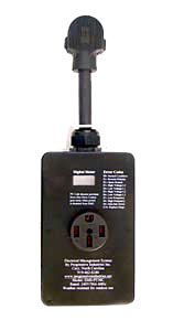
A 50-amp portable surge protector from Progressive Industries
In the images above, we can see two portable surge protectors. Portable units have the advantage of being able to be readily moved from one RV to another. This makes for a zero installation setup with no rewiring. Just plug it into the campground pedestal and plug the RV’s power cord into the surge protector. The disadvantages are that it is out in the weather and could get stolen or vandalized. There are locking kits available to lock them to the pedestal but then you are trading the convenience of not having the initial install versus connecting it and securing it to the pedestal every time you go camping. If the pedestal’s receptacle is very low to the ground it’s possible that the portable unit may not fit because of the right angle plug and the bulk of the unit that needs to hang down from the outlet. One last caveat is that the hard wired units sometimes offer a remote display option so that you can monitor the incoming power from inside the coach. With a portable unit you won’t be able to utilize that option. The actual protection levels of the portable units are generally the same as their counterparts in the hard-wired segment so there’s no advantage or disadvantage there.
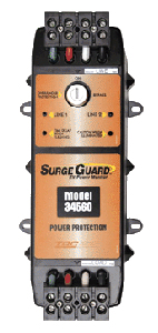
Surge Guard 50-amp hardwired surge protector
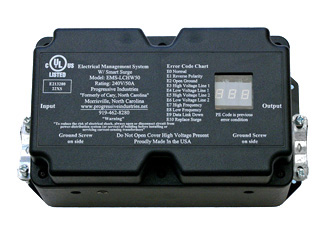
A 50-amp Surge Protector from Progressive Industries
Hard-wired devices do take a bit of installation labor but it’s not that difficult. You simply mount the unit in the same electrical compartment that your RV’s cord is located in. Remove the power cord from the transfer switch and connect the cord to the surge protector’s input terminals. Then run a short whip cord from the surge protector’s output to the transfer switch and you’re all set. Some RV owners choose to just cut 2-3′ off the end of the power cord while some choose to buy another short chunk of cord from a home improvement store. If you have a power cord reel you’ll undoubtedly be buying a new whip. If your surge protector includes a remote display you will have to find a location for that display, mount it, and then connect it with a standard RJ11 modular phone cable. A cable is generally supplied but if you want to run a longer distance you may have to make a new, longer cable to reach the remote display panel.
Surges are rated in Joules. The bigger the surge, the higher the number, so you want to get a surge protector with the highest possible rating. The popular Surge Guard 34560 is rated to handle up to 1,750 Joules of power surge. It will shut down power to the coach if the voltage falls below 102 Volts or is higher than 132 Volts. Various LEDs will inform you whether the receptacle is properly wired or has a bad ground, reversed polarity, or open neutral. If it shuts down the power due to low or high voltage or an open neutral wire it will reset itself once the power returns to within tolerances. There will be a two minute, 15 second delay before power is re-energized though to allow any air conditioners time to bleed off their head pressure. If you decide that you want to bypass the voltage cutouts feature and allow power through you can defeat the unit by turning a key switch. In this mode you will still have surge suppression, however. Surge Guard also makes automatic transfer switches with built in surge protection and low voltage protection. These transfer switches are becoming very popular in recent diesel pushers due to their ability to also communicate with a multiplexed network control panel.
The Progressive EMS-HW50C is the gold standard of surge protectors. It’s rated to handle up to 3,560 Joules of surge. Low voltage cutoff occurs at 104 Volts and high voltage cutoff occurs at 132 Volts. It comes with a remote LED display that is very easy to read. In addition to displaying the incoming voltage of both poles it will also display the amperage draw on each pole as well as the frequency in Hertz. If any pedestal mis-wiring is present or any shutdown has occurred the LED display will display a 2 digit trouble code that defines the problem according to the chart that is printed on the unit as well as in the owner’s manual. The remote display can be mounted inside the coach or in the basement compartment. In this way it’s handy to locate the EMS-HW50C near the back of the compartment where it’s easy to wire and still have the remote display located near the front of the compartment where it is easy to view. The bright LED is easy to read in bright sunlight and a bypass switch is located on the remote display to bypass the power shutdown function, just like in the Surge Guard above. You have the choice of selecting either a 15 second power-on delay or a 136 second delay. Most modern air conditioners have a built in two minute restart delay so 15 seconds is the normal selection. You can also buy a second remote display that allows you to mount one in the basement and one inside the coach if you desire.
While the EMS-HW50C is the old standard, Progressive Industries also make the EMS-LCHW50 surge protector. The “LC” stands for Liquid Crystal display. Instead of a remote LED display, the LC series uses an integral liquid crystal display that is located right in the cover of the unit. The protection level is the same as its big brother but, depending on where the unit is mounted, you may have more problems in viewing the display. LCD screens just aren’t as bright as LEDs and dark places and bright places are not their friends. Coupled with the fact that the remote LED display can be located anywhere and the LED holds a huge advantage. Still, the LC series does hold a $50 price advantage over its more costly brother.
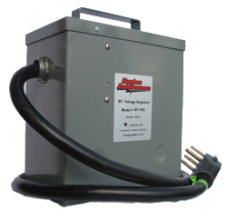
The Hughes Autoformer will boost low voltage
Once your surge protector determines that the campground voltage is below the minimum acceptable level it shuts down power to your coach. If you really want to power your coach you have some decisions to make. You can go turn the key or flip the switch to bypass your surge protector’s low voltage cutoff feature. You have to wonder if that’s a very safe thing to do though. After all, the reason it shut down is to protect your coach from low voltage. Remember that wattage is true power and volts times amps equal watts. If a device in your coach needs a certain amount of watts and the voltage falls, the amperage will rise and those excess amps will overheat and damage your circuitry. Another option is to run your generator. That may or may not be desirable, depending on your environment and neighbors. You can always wait it out in case it returns once the sun goes down and everyone’s air conditioner stops running non-stop. Or, you can get an Autoformer.
An Autoformer is a voltage booster. While they do offer some surge protection, it’s main claim to fame is it’s boost technology. An Autoformer will automatically boost the incoming voltage. Models such as the Hughes Autoformer RV 450 will boost the voltage 5-10-15% as needed. That gives you the ability to take an incoming voltage as low as 91-92 volts and boost it to the minimum 104-105 volt cutoff that the surge protector needs to see. If used in conjunction with a surge protector the Autoformer is always mounted first so that it boosts the voltage prior to the surge protector. If it was mounted after the surge protector it wouldn’t work because it would kill any input voltage to the Autoformer and the Autoformer needs to see something before it can boost anything. The Autoformer is an optional piece of equipment. If you don’t feel that it’s that critical that your coach have power at all times or if you camp at nice RV resorts that have clean power you may not feel it is necessary. If you have a coach with a residential fridge and happen to encounter low pedestal voltage frequently then it may be a life saver that will save you from having to run your generator frequently. The Autoformer doesn’t get very hot and it can usually be mounted in the same compartment as the surge protector and power cord reel. In that case a hard-wiring kit is available that lets you splice into the cord reel’s output whip so that it can be inserted into the power cord whenever necessary. This keeps it safe and dry rather than sitting next to the pedestal exposed to the elements and potential theft or vandalism.
That’s it for this month. This is third and final installment of this series. I hope I didn’t bore you too much. Hopefully you’ve gained enough knowledge about how your motorhome’s electrical system operates. Now – go out and buy that multimeter if you don’t have one.

Mark Quasius is the founder of RVtechMag.com, the past Midwest editor of RV Magazine, writes for numerous RV-related publications and a regular Contributor to FMCA’s Family RVing Magazine. Mark and his wife Leann travel in their 2016 Entegra Cornerstone.

