RV Electricity 101 – Part 3 An RV Owner’s Guide to RV Electrical Systems

Last month our tutorial covered batteries, generators, transfer switches and inverters. This month is part three, our final installment of this three part series on RV electrical systems. We’ll get into solar power, surge protection and energy management systems.

Low Voltage Circuits:

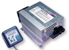
Motorhomes are meant to be used when 120 volt shore power is not always available. It would be a real pain if every time you walked into your motorhome you had to fumble around in the dark to start the generator so that you could turn some lights on, which is why RVs have 12 volt battery powered electrical systems as well as 120 volt AC electrical systems. The 12 volt system provides power to operate the interior lights and the many other 12 volt electric systems within the coach, such as fans, water pumps and furnaces. These systems will be connected to the coach battery bank via a 12 volt fuse panel that is located somewhere inside the coach. A converter or inverter/charger will also be connected so that these batteries can be recharged from shore power or when running the generator.
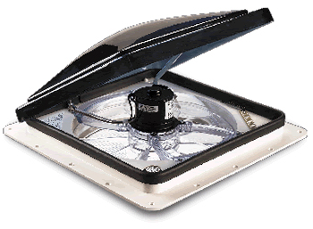
Powered Roof Vent

Powered vent fans are commonly used in most RVs.

Powered roof vent fans, such as the one pictured above, are found in most every RV. In addition, you’ll undoubtedly find that you have a tank monitoring system to check the levels of your fresh water, propane tank, and holding tanks. This information may be displayed on a small remote panel or incorporated into a networked touch screen control panel. Your refrigerator and hot water heater are designed to run on either 120 volt AC current or propane. But, you will need 12 volt power to operate the igniter and the control circuitry for any propane fired refrigerator. Even the light bulb inside that fridge is powered by 12 volt power. Basement compartment lighting and power awnings are other examples as is the power steps that allow you to enter your motorhome.
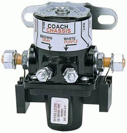
battery disconnect solenoid

A typical battery disconnect solenoid.

If you were to leave your motorhome parked for a while and shore power was not available, the various parasitic loads on the 12 volt circuits would eventually drain the batteries. RVs have a battery disconnect switch, which is generally located close to the entrance door. This switch controls a battery disconnect solenoid. This solenoid is a latching solenoid which means you send it power to move it but you do not have to continue feeding it power in order to hold it in that position. This makes it perfect for an RV application because the solenoid won’t consume any battery power when parked. Pressing the rocker switch in one direction will shuttle the solenoid to the open position while pressing the rocker switch in the opposite direction will send the shuttle in the other direction and close the circuit. This allows for an easy way to shut down the 12 volt power to the coach while you are away. If you are plugged into shore power, this is not necessary. Keep in mind that not everything will be disconnected when the solenoid is in the off position. Some loads, such as inverters, keyless entry systems and propane leak detectors bypass the solenoid and will remain active.
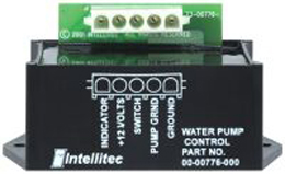
water pump controller

Typical water pump controller

Your fresh water tank needs a water pump in order to pump water from the tank to the faucets when you are not connected to a campground’s pressurized water supply. This pump generally has a number of switches located by the various plumbing fixtures so that you don’t have to run to a central panel to turn on the water pump. In order to allow all of these switches to control one water pump a water pump controller is used. A water pump controller is another latching relay that allows a number of switches to send a small trigger signal to turn the controller’s relay on or off. The relay will then take a larger 15 amp power feed and send it to the water pump to turn it on. The controller also sends out an “on” signal to all of the indicator lights that are located by the switches throughout the coach so that the user knows whether the water pump is on or off.
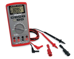
voltmeter

A multimeter is an indispensable tool for every RV owner

Sometimes these systems can fail, not that this will come as a shock to anyone. When electrical systems fail it’s time to do some testing to see where the failure is. A voltmeter is a huge help in this area although a test light can also be used to test low voltage circuits. Personally, if you are a motorhome owner you should have a multi-meter of some sort. It’s invaluable for checking high voltage circuits, campground pedestals, low voltage circuits, and continuity.
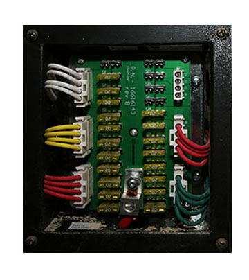
Fuse Panel

Fuse panels hold fuses for all 12-volt systems.

The first thing to do is to check for blown fuses. Sometimes you can do this by removing the fuse and holding it up to the light to determine if the fusible link is blown. Sometimes it’s not so easy to see. The way many of these fuse panels are labeled, or more accurately, “not” labeled, you may have trouble figuring out which fuse does what. The common ATO fuses are blade type fuses with a plastic housing. There are bare spots on the end of the housing that can be used to test for voltage. If you have power going into the fuse, but not out of it, you’ll know you have a bad fuse. Another method is to use the ohms setting on a multimeter. Remove the fuse and check for continuity with the meter. If no continuity, the fuse is bad. If you have a critical circuit you can also replace those fuses with ATO style circuit breakers that plug right into place. There are also fuses with LED pilot lights that will illuminate if the fuse is blown. So, you have lots of options when it comes to fuses.

If it’s not a fuse, then you need to look a little deeper. If the fuse does have power leaving it, test for voltage at the device that isn’t working. If you have power coming into the device it’s either a bad device (light bulb, fan motor, water pump, etc.) or else you do not have a complete circuit. In that case I’d check for a bad ground because an open ground won’t give you the complete circuit back to the battery. If you do not have power at the device there is an open circuit between the fuse and the device. The first place to look would be at the switch. Test to see if there is power coming into the switch and power exiting the switch. If the power is getting to the switch but not leaving it, it’s time to replace the switch. 

Wire Gauge (AWG) Wire Diameter, in Inches Current Capacity, in Amps
0000 .4600 600
000 .4096 500
00 .3648 400
0 .3249 320
1 .2893 250
2 .2576 200
4 .2043 125
5 .1819 100
6 .1620 65-80
8 .1285 40-50
10 .1019 30-33
12 .0808 20-23
14 .0641 15-17
16 .0508 7.5-10
18 .0403 5
20 .0320 3.3
24 .0201 1.3
28 .0126 0.5

This chart shows the current capacity for various wire gauge sizes.

Above is a wire gauge capacity chart. Wires are just like water pipes in that you can only pump so much stuff through a given size pipe without losing pressure. If you try to send too many amps through too small of a wire the voltage will drop, the wire will get hot, your device won’t run properly, and you’ll probably blow the fuse for that circuit. The above chart serves will give you a good idea as to what wire gauge you will need to use if you want to add an accessory to your RV. For example, if you want to add a small fan to your RV that has a motor rated at a 4 amp draw you will need to go with a #18. The 20 gauge wire is only rated for 3.3 amps while the #18 can safely handle up to 5 amps so you always round up. If you want to install a water pump that pulls 20 amps, you’ll need to use a #12 wire. If you want to add an inverter and its DC battery draw is 400 amps you will need a #00 wire. Keep in mind that you can always go to a larger wire gauge without any bad results but you can never go smaller. Also, the length of wire will also affect its ability to carry current. If you are running long runs of wire you may need to increase the wire gauge to allow for the extra resistance incurred by the extra lengths. In this case, use the above wire gauge chart conservatively when choosing which wire gauge to use. Going larger is always a safe bet.

Inverters:

As we learned earlier, inverters do just the opposite of converters because they create 120 volt AC power from 12 volt DC battery power. In actuality they don’t “create” the power, they transform it. An inverter uses electronic signal processing circuitry and transformers to bump the 12 volts up to 120 volts and change the DC current into AC current. The electronic circuitry creates the proper frequency and voltage levels that make up the waveform of the output current so while the inverter doesn’t really create power, it takes existing power and molds it into a different output. In the process of doing so there will be a slight loss of between 6 and 15% so just because you are inputting 2,000 watts of battery power doesn’t mean you’ll be getting the full 2,000 watts as output.
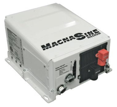
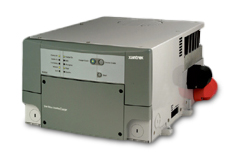
A Magnum true sine wave inverter/charger

A Magnum true sine wave inverter/charger.

Inverters are available in many sizes. Inverters can be as small as 175 watts. These units can plug into a 12 volt power socket and be used to power a small power tool. Larger inverters can be direct connected to a battery source and mounted in an RV’s cabinet to power TVs or other entertainment equipment. Some of these inverters can run 1,000 watts, or even 1,800 watts in size. The second style is the inverter/charger. These units are larger and designed to handle multiple circuits and typically range from 2,000 watts to 3,000 watts in size. They also provide battery charging capability so when an inverter/charger is used the converter is eliminated because it’s no longer needed.
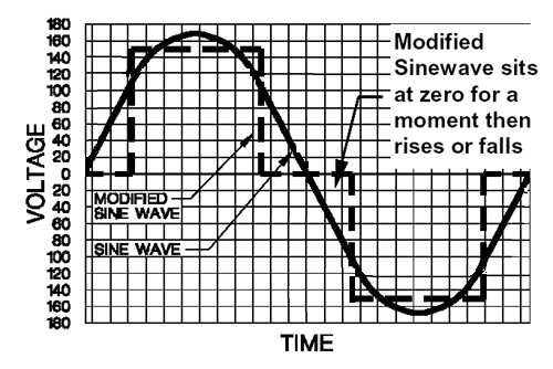
true sine wave and modified sine wave chart

Chart showing difference between true sine wave and modified sine wave

Inverters may output one of two waveforms. The waveform that is output by a generator set is a true sine wave. The power put out by your public utility is also true sine wave because it too is created in a generator, even though it’s a very large one. The voltage will rise and fall like a large S-curve as the field passes by the magnets in the generator. This creates a wave where the peak voltage appears for an instant, then falls back down to zero. However, peak voltage is meaningless. Your equipment is designed to run on 120 volts RMS (Root Mean Square) voltage, which is the voltage level at a given width of the wave. Voltmeters will also read RMS voltage so there are no calculations or anything complex to have to worry about

Inverters do not have rotating parts and magnets. Instead, they create the desired waveform and frequency electronically. The earliest inverters were known as modified sine wave inverters. The waveform created by these inverters took a straight vertical leap to a given level, then traveled in a straight horizontal line for a given time, then fell instantly back to zero volts and rested for a while before repeating this cycle over and over again. Unfortunately, this power can create issues with sensitive electronics equipment and electric motors because it is not a true sine wave. A standard voltmeter will read this as a much higher voltage, probably around 150 volts rather than 120 volts. It takes a special voltmeter to take modified sine wave readings. The biggest problem is that electric motors and integrated circuits get messed up by this as well. But, at the time there wasn’t that much high tech stuff on the market and modified sine wave inverters were an affordable alternative.

As electrical components became more complex, so did the need for inverters with a cleaner waveform. The advent of the true sine wave inverter gave us that ability. Fortunately, as electronics improved, so did the ability to make cost effective true sine wave inverters. A true sine wave inverter perfectly matches utility power and there are no longer any limits to what can safely run on it. The graph above shows the difference between the two sine waves. If you are running simple things, such as lighting, you won’t really have an issue with modified sine wave. Modified sine wave inverters will power toasters, lights, microwaves, any electrical heating element, as well as most motor loads such as refrigerators, vacuums, etc.

Electronics do not fare as well on a modified sine wave. Digital clocks will not keep accurate time. Many small battery chargers, such as used on cordless power tools will not function correctly. And any electronic device is subject to failure. The biggest issue is that all major appliances are now becoming heavily interfaced with electronics. While your refrigerator’s compressor motor may run fine on modified sine wave, the electronic control panel in the door that controls the water dispenser and ice maker may not like it and will fail. Microwaves ovens will function but the electronic control panel may not hold up that long. In fact, you will most likely hear the difference between shore power, which is true sine wave, and when on the modified sine wave inverter as the microwave labors when on the inverter.

Laptop computers will run fine because the inverter is merely powering a battery charger. The battery itself acts as a buffer and runs the laptop on DC power, even when plugged into the AC adaptor. Desktop computers are not in the same category though and you will probably damage them quite quickly. Modified sine wave inverters will also generate RF noise in the line so you will have issues if you try to power a ham radio with one. Motor speed controllers using triacs won’t work properly either. If there is a “wall wart” power supply box plugged into the wall you’ll be fine though. Inkjet printer models can be either way on this so check first. Generally, if you see the current transformer on the power supply, you’ll be fine.

Inverter Operation

A simple inverter isn’t that hard to figure out. It connects to a battery power source and you plug your AC load into the receptacle. You turn it on and it works. Larger inverter/chargers are a bit more complex. An inverter/charger also has a 12 volt DC battery input and a 120 volt AC power output. These units are larger so they are generally hard-wired into the coach’s electrical systems. The inverter also has a 120 volt AC power input connected to it as well. Inside the inverter is an automatic transfer switch to handle switching of the inverter’s AC output from between the inverter created power and the 120 volt bypass power. Whenever you are plugged into shore power or the generator is running, there will be 120 volt power present at the inverter’s bypass power inputs. The inverter will simply pass that power through to the inverter’s output. This is referred to as pass-through or bypass power. Whenever 120 volt AC power is not present at the inverter’s inputs the inverter will create (“invert”, actually) AC power from the 12 volt DC batteries and the transfer switch will flip over to the inverter’s own power output to feed the desired devices. Because of this it is not necessary to turn the inverter off and on because the transfer switch will handle the changeover in power sources automatically

Whenever pass-through power is present the inverter/charger also acts as a battery charger. In addition to passing through the AC input current, some of that power is drawn off to operate the battery charger mode of the inverter/charger. Instead of drawing power from the batteries to make 120 volt AC output, it now uses the available AC input power to help put some power back into the batteries by recharging them. Modern inverter/chargers utilize 3 stage battery charging algorithms. Initially it will output up to 14.8 volts as needed in a bulk charge mode. As the batteries near completion the charge will taper off into an absorption mode. Finally, the charger settles into a float mode where the charge voltage will not exceed 13.2 volts. This is a maintenance mode designed to hold the battery at its fully charged state while at rest. Inverter/chargers do have on/off buttons to disable either or both functions but they are not normally needed because the inverter/charger will automatically switch back and forth as needed. However, when the coach is stored it’s not enough to switch off your output circuits. An inverter will have a slight idle current even while not in use if it is allowed to be powered up. When storing your coach without shore power be sure to switch off your inverter and charger at the inverter itself to eliminate the idle current from slowly draining your batteries.
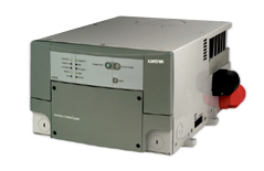
Xantrex 2,000-watt true sine wave inverter/charger.

A Xantrex 2,000-watt true sine wave inverter/charger

Inverter Installation

If your RV doesn’t have an inverter, but you would like to install one, be sure to download a copy of the manufacturer’s installation manual from their website and read it first before buying your inverter. Inverters do need the proper environment. True sine wave inverters can create a fair amount of heat. If you place them in a large basement pass-through storage area you’ll be fine but if you place them in a small enclosed compartment they will overheat. In that case you’ll need to provide some intake air as well as a place to exhaust the heat, preferably with a fan. The next consideration is providing battery power to the inverter. Larger inverters need lots of battery amps in order to provide power. This means large diameter battery cables are required. You also need to keep the length of these cables short so you’ll want to locate the inverter close to the batteries rather than run huge cables a long distance. Again, refer to the manufacturer’s manuals for specific details.

You’ll also need to fish a network cable from the inverter to a handy location where you will mount the remote display panel that controls the inverter. You’ll also need to run another cable as you connect to the battery temperature sensor that needs to be mounted on the batteries. Lastly, you’ll need to run AC wiring from your main breaker panel to power the inverter and then run the inverter’s AC output to a sub-panel so that you can feed all of the desired circuits that you want the inverter to handle. As the inverter size increases, so do the difficulty levels of all the above tasks so plan carefully before spending your money. You may find it best to have the installation done by professionals if this kind of work is out of your wheelhouse.

Automatic Generator Starting:

Automatic Generator Start (AGS) systems do just what you think they might do – they start your generator set automatically, even if you are not near the coach. These systems vary in complexity and design. Some systems are standalone systems and are simply a module that connects to your generator set to start it if your batteries get low. Some systems, such as the Onan EC-30, are an all-in-one system that builds the circuitry into its remote display and control panel. This system design also includes a thermostat interface so that it can start your generator in response to a request for cooling from the air conditioner’s thermostat. Other systems, such as the Xantrex and Magnum AGS modules, are designed to network with an inverter and use the same remote display panel as the inverter to control both the inverter and AGS module via menu driven software. So there are a number of options and choices available when selecting an AGS module.
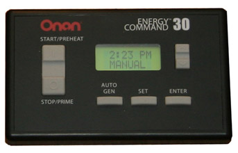
Onan EC-30 Automatic Generator Start (AGS) module

The Onan EC-30 Automatic Generator Start module.

Selecting an AGS System

The first thing to do is determine just why you want an AGS system in the first place. If you are only going to run your generator to power air conditioning when driving you probably don’t need one. If you will be dry camping quite often you will need to run your generator every now and then to recharge your batteries. If your batteries drop below a given voltage your AGS can start the generator set for you automatically while you are off sightseeing so that you don’t return to a dead coach. This is the basic feature of any AGS system. You can also recharge your batteries while you sleep if they drop down during the night without having to worry about setting your alarm clock. Many campgrounds do have a quiet time posted where no generators may be run during the evening but more advanced AGS models include a quiet time setting that can be set. In that case the AGS module will not start your generator during those quiet time hours and will wait until morning to auto-start. Some models, like the Onan EC-30, include predictive scheduling. The AGS will monitor your battery voltage level and if it determines that it will need to recharge them during quiet time, it will start the generator earlier and then shut off so that they will be recharged when your quiet time begins.

The next level includes a thermostat interface. Your AGS system will be connected to your air conditioning system’s thermostat. If a request for cooling occurs, the AGS will start your generator and power the air conditioning system to prevent your coach from overheating. Some systems also include a shore power connection so that the AGS will only start the generator if there is no shore power present. This is a great feature for RV owners who have pets and normally camp in full service campgrounds. The shore power will power your coach’s air conditioners to keep your pets from overheating. But, what happens if the shore power was to go out or the pedestal breaker tripped while you were away from the coach? Your air conditioners would stop working and you might be returning to a coach with pets that suffered heat stroke.

If you have an AGS that does not have a shore power sense, but does have a thermostat connection, you’ll find that the generator will start up every time the thermostat calls for cooling – even when the shore power is functioning. This is not desirable so you will have to install a relay that is fired by the shore power side of the transfer switch and then intercept the low voltage wires that connect the thermostat to the AGS module. This will break the circuit whenever shore power is present so that the AGS never sees the input signal from the thermostat. When the shore power fails the relay will allow that connection to take place. With an AGS that has shore power sense you won’t have to worry about that. All of the logic is handled within the AGS electronics and it won’t start the generator if shore power is present. If shore power fails and cooling is desired it’ll start the generator and your pets will be safe.

If you have a Silverleaf or Firefly networked whole coach system that controls most coach functions via a multiplexed network you most likely have a bridge, which is a device that bridges the communication with the inverter/charger and the Vegatouch control system. This allows complete control of the generator and AGS module via the master control touch screen in the coach.
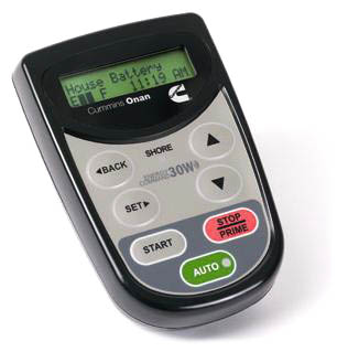
wireless controller for the Onan EC-30W AGS module

The Onan EC-30W AGS unit uses a wireless controller

Installing an AGS module requires a bit of work. You need to run wiring connections to the transfer switch mounted transformer as well as the batteries, generator start-stop switch, remote control panel and HVAC thermostat. Fishing all of those wires can be tedious and sometimes difficult. Wireless units will save you some time by allowing those connections to be performed under the floor in the chassis area, using wireless operation to the remote display panel in the RV. The Onan EC30W is the premier wireless system. The remote unit communicates wirelessly to the main harness and even contains a temperature sensor so that you don’t have to tap into the existing HVAC thermostat. You do have to be careful of where you place the remote though. If you set it in a hot spot it’ll be triggering the generator prematurely. You also run the risk of communications failure, which can happen with any wireless electronic device, particularly when you consider that the signal needs to pass through the motorhome’s steel firewall.

Solar Power:

Solar panels are widely misunderstood. The most common question posed is “How many solar panels do I need to run my RV?” But, the fact of the matter is that solar panels don’t run anything. It’s your batteries that will provide enough amp-hrs to power your electrical devices. Solar panels don’t output enough amp-hrs to run a device but they will continue to provide that slow and steady output over a fairly long time frame so in effect, solar panels are strictly battery chargers. Your electrical devices will draw amps from your batteries but solar panels will put some amps back into those batteries. Unless you have a massive solar panel array or are a real miser with your power consumption, you’ll never be able to keep your batteries from running down. Eventually you will need to run your generator to recharge those batteries and bring them up to a full charge. However, solar panels can add enough extra amps to extend the timeframe between generator runs so that it occurs at a time that’s more convenient for you.
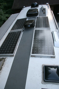
solar panel array featuring four 120-watt panels on a 40’ coach

A solar panel array featuring four 120-watt panels on a 40’ coach

One of the biggest limitations of solar panels is that you need enough of them to make a difference. If you think that slapping a 50 watt panel on the roof is going to do something, then you are wasting your money. Unfortunately, panels take up some room and not every RV roof has an overabundance of that. The image above shows an array of four 120 watt panels on a 40′ coach. It was possible to place two on each side and still be able to walk down the center of the roof for service access on the gray non-skid surface. One of the biggest limitations of solar panels is that you need enough of them to make a difference. If you think that slapping a 50 watt panel on the roof is going to do something, then you are wasting your money. Unfortunately, panels take up some room and not every RV roof has an overabundance of that. The image above on the left shows an array of four 120 watt panels on a 40′ coach. It was possible to place two on each side and still be able to walk down the center of the roof for service access on the gray non-skid surface.
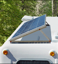
Solar panel with tilt mounts

Solar panels with tilt mounts align the panel to the sun for better performance

Solar panels create the most power when they are getting direct sunlight and lots of it. They can be ordered with flat mounts or tilt-up mounts. Tilt up mounts have the advantage of being able to be aimed at a southern exposure so that the solar panel can receive more light throughout the day. You do have to park the RV so that the panels are facing south though and that’s not always an option. Also, if you forget to put them down and lock them before driving away you’ll be buying new panels and patching some holes in the roof where they used to be mounted to. Overall, flat panels are the safe bet for a motorhome. The benefits of an adjustable mount just aren’t that much that it pays to put up with the hassles they bring unless you are staying in one place for a long time.

Solar panels vary in output but it’s proportional to their size. You won’t find a panel that has significantly higher output than another in the same physical size. The biggest difference in panels is their ability to produce power under less than optimal conditions. Unfortunately, there is no rating method or specs that will tell you this so you’ll have to rely on information from other owners or a sales rep that you can trust. Some panels will put out their maximum rated output when it’s nice and bright but fall off sharply when the light is dimmer later in the day, early in the morning, or when it’s overcast. Some panels continue to produce respectable light output under less than optimal conditions. Those are the ones you want to have because it’s all about the total amp-hrs output during the day, not just what’s happening at high noon.

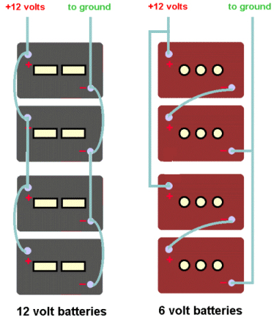
You’ll need to determine just how many amp-hrs you’ll be using during a 24 hour period. Take the wattage of any 12 volt items, such as lights, fans and blower motors, and divide by 12 to find the amps. Then multiply that number times the numbers or hours (or portion of an hour) that each item will be run during that day. Make a note of that number. Then do the same for all of your 120 volt loads except divide those wattage amounts by 10 instead of 12 to find out how many 12 volt amps will be needed to feed the inverter. This will allow for a 20% inverter efficiency loss, which is more than adequate for planning purposes. Add everything up and that’ll tell you how many amp-hrs you’ll need to run everything during a 24 hour period. Go look at your battery bank size. A typical four battery bank of 6 volt golf cart style batteries should be around 440 amp-hrs in size at 12 volts. You don’t want to run these batteries below approximately 50% charge level so you should limit their use to 220 amp-hrs before recharging them. If your above calculations show that you are consuming more than that, you won’t make it through the day. Calculate the difference between what you need and what you have and that’s your shortage. If you can install solar panels to exactly supplement that amount you’ll be able to make it 24 hours before recharging via the generator.

If you are an avid boondocker chances are you’ve figured out ways to minimize your power consumption. By doing the above math you may find that it’s possible to camp for a number of days before needing to run the generator. Solar panels can help extend that as well. Remember that we said earlier that solar panels don’t run anything. What they do is provide “free” amp-hrs of battery charging power that can help extend your recharge times to where it is more convenient for you. One other option is to just add more batteries. Extra batteries will cost you far less than solar panels so if all you are looking for is a few extra hours between charge cycles I’d look at adding batteries. If you do decide that solar panels are a good fit for your RV style then you still may want to add additional batteries. If you use AGM batteries rather than flooded batteries you’ll also get more runtime. This was discussed earlier in the Batteries chapter. Another way to maximize your solar panel output is with a good charge controller.
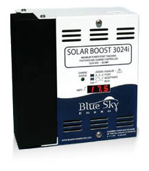
30-amp MPPT solar charge controller

A 30-amp MPPT solar charge controller
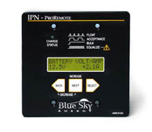
Blue Sky charge controller

A smaller Blue Sky charge controller

Charge controllers connect between your solar panels and your batteries. They vary greatly in price and capabilities. The simplest charge controller acts as a diode, or check valve, to prevent dark current. Without this check valve your battery current would drain into the solar panel at night. The charge controller is a one way valve that prevents dark current from happening so that your batteries can retain their charge. Whenever the solar panel output voltage falls below the battery voltage the charge controller opens the circuit between the two. The second function that charge controllers do is to provide voltage regulation. In bright sunlight a solar panel may produce 18 volts or more. The battery doesn’t need or want that kind of voltage so the charge controller regulates it to a safe level. Simple charge controllers generally have a low wattage rating, usually 15 to 20 amps, and are mounted into a hole cut into the wall. There’s nothing very fancy about them and they are inexpensive. The next step up is a charge controller that features 3 stage charging. Just like our inverter/chargers and converters there will be a bulk charge, absorption charge, and a float charge. These can be wall mounted or larger units located in a basement compartment. They could be as low as 20 amp or much higher. The larger sizes, such as 30 and 50 amp usually offer an optional remote control panel that can be mounted inside the RV to monitor operation. One real benefit is in getting a charge controller with MPPT (Maximum Power Point Tracking) technology.

MPPT technology makes a huge difference in solar panel output and it really doesn’t pay to go with solar without an MPPT controller. Remember our earlier discussion about amps, volts, and watts? Wattage is true power. Amps times volts equals watts. Solar panels have a fairly high maximum output voltage, which drops as the light intensity fades. A 120 watt panel that’s outputting 16 volts will give you 7.5 amps of current. Your battery doesn’t really care what voltage is coming in. As long as the incoming voltage is higher than the battery voltage it’ll take a charge. All it really wants is to see some amps. If we were to modify that 120 watts of power and drop the voltage down to 12 volts we would have 10 amps of battery charging current. A simple non-MPPT controller merely clips off the excessive voltage, wasting valuable amps in the process. But, an MPPT Controller will trade volts for amps and you’ll get some free current that you wouldn’t otherwise have gotten. On the average an MPPT controller will give you 30% more charging power over a non-MPPT controller. It’s like getting a free extra solar panel in the bargain.

One other feature is voltage transformation. Solar panels can be connected in series or parallel. If they are in arranged in parallel the voltage remains the same but the amperage is multiplied by the number of panels. For instance, a 120 watt panel should theoretically put out 10 amps each at 12 volts. A bank of four of the connected in parallel would yield 40 amps at 12 volts, which is equivalent to 480 watts. If these panels were connected in series they would produce 10 amps at 48 volts, which is also 480 watts. The problem is that our batteries are 12 volts, not 48 volts. But if we had a charge controller that was capable of taking a higher voltage input and transforming it to a lower voltage output it would work. One such charge controller that will do that is the Outback FLEXmax MPPT Charge Controller. It’s available in 60 amp or 80 amp versions and can take an input level as high as 60 volts and output it as 12 volts. The benefits to this are several.

First of all, wire gauge is relative to how many amps it will carry. As we saw earlier in our wire gauge charts, 40 amps requires a larger #8 wire while 10 amps can get by with a much smaller #16 wire. This can make it much easier, and less expensive, to install. Secondly, when the sun begins to set low on the horizon the lighting level is diminished. A 12 volt array may only be capable of 10 volts at that time so you won’t be getting any more power from those solar panels. But, if it was a 48 volt array you would still have 40 volts left over for the charge controller to convert to 12 volts and feed the battery bank. This will give you even more amp-hrs per day. Voltage step-down controllers such as the Outback isn’t the cheapest controller available but it appears to be the best at maximizing your solar panel array’s output.

Energy Management

Energy Management is simple – you just need to make sure that you don’t use any more power than is available. Battery power is finite. Eventually it’ll run out. By minimizing how many lights are on and the time they are on, battery life can be extended. Eventually you’ll need to recharge them, either by driving the coach or by running the generator. Adding extra batteries can extend that runtime as can the addition of solar panels. If you are plugged into shore power this isn’t an issue because your converter or inverter/charger will keep them charged while you use them.

AC power is a bit different. Unlike battery power, there is no reserve to draw from. You are limited to the total current capacity of your shore power pedestal or your generator’s capacity. Generators are generally sized for that particular coach so you should be able to run whatever loads you need to operate without exceeding the generator’s capacity. Of course there are exceptions where an undersized generator was specified in that particular coach rather than choosing the optional generator but those are the exception, not the rule.

Shore power pedestals vary in size. If you are running a small 20 amp cord to your RV from someone’s home you’ll be very limited as to what you can run. Battery chargers vary in current draw as to how many battery amps they are outputting. A battery charger that is outputting a full 100 amp bulk charge at 12 volts will be drawing 10 amps of 120 volt AC power. That can take up one half of your 20 amp circuit, which doesn’t leave a whole lot left. Many inverter/chargers have a setting on the remote control panel to define the shore power service. If you define the shore power at a lower level, say 20 amps, then it will limit the 120 volt power that they battery charger uses so that you can have more left to run other 120 volt items. You will need to manually set this once you are plugged into a smaller shore power pedestal.
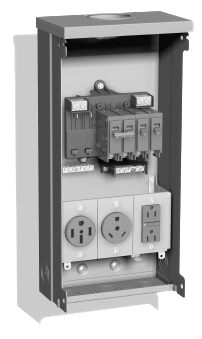
RV pedestal with multiple 50-30-20-amp receptacles

A typical RV pedestal with multiple 50-30-20-amp receptacles

In the above image we can see three receptacles. This is a typical 50 amp pedestal which features a 50 amp, 30 amp, and 20 amp outlets. This pedestal allows virtually any type of RV to be serviced with power. The 50 amp outlet is a 120/240 volt split-phase outlet, capable of 12,000 watts of total power. If you have an RV with 50 amp service you should have no problems powering your RV’s electrical appliances when plugged into a 50 amp outlet. Older pedestals may only be configured with a 30 amp outlet however. This is a single pole 120 volt feed, capable of 3,600 watts of total power. You can adapt your 50 amp coach to this 30 amp outlet via a dogbone adaptor but you will be severely limited in just how much you can run in your RV. If the battery charger is pulling 5 amps and your two air conditioners are pulling 12 amps each you’ll be drawing a total of 29 amps. All it takes is for the electric water heater element to kick in or someone turning on the microwave and you’ll trip the pedestal breaker and you’ll be making a trip out to the pedestal to reset it, which of course always happens when it’s raining.

Manual energy management entails turning off some loads so that you can turn on others. If you really need to get hot water it would be best to use the propane burner instead of electric if it’s hot out. If you need to use the microwave for a bit then you’ll have to shut down one of the air conditioners so that amperage can be used by the microwave temporarily. Eventually this gets to be tiring and you’ll either find places to stay at that only have a 50 amp service or you’ll wish you had an automatic energy system.

Automatic Energy Management Systems

An Energy Management System (EMS) automatically performs the circuit switching procedures for you. Do not confuse a true EMS system with surge protection. Some name brand surge protectors use the term EMS in their models and descriptions. In a way, this is true because they do more than stop surges. They also protect from low or high voltage but they are still part of the surge protectors category. True EMS systems do not consider voltage levels. They only monitor the amperage draw and perform shedding of various circuits to keep the total power consumption beneath the pedestal breaker rating.
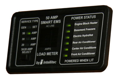
remote display panel from the Intellitec Energy Management System

The remote display panel from the Intellitec Energy Management System

The most popular Energy Management System of years back was made by Intellitec. The Intellitec system consists of a custom breaker panel which has four 120 volt relays and two low voltage relays. These relays are controlled by a proprietary electronic module that turns these relays on and off as needed. The board senses the power that is coming into the breaker panel. If it sees 240 volts across L1 and L2 it knows that it is a 50 amp feed and it performs no energy management tasks. If it sees 12 volts at the terminal that is connected to the generator’s hour meter it knows that the generator is running. In this case it will display the amperage on the remote display panel but will not perform any load shedding tasks. If the generator run signal is not present and 240 volts is not present it will know that you are on a 120 volt single pole shore power feed. It will default to a 30 amp setting but you can change it to 20 amps if you need to by pushing that button on the remote display panel. In this mode it will display the amps being used and shed any circuits that need to be shed in order to remain underneath the 30 amp (or 20 amp if selected) limit of the pedestal breaker. The loads are shed according to a pre-determined load shedding order, whereby the least critical circuits are shed first. The biggest drawback to this system is that the breaker panel is quite large at over 20” in width, which makes it difficult, if not impossible, to install when retrofitting a coach without an EMS. This system has since been discontinued and RV manufacturers are now going with a newer, more technologically advanced unit by Precision Circuits, Inc.

Let’s assume that you want to run two air conditioners (at 12 amps each), the electric water heater (at 10 amps), and your battery charger (4 amps in float mode). That’s a total of 38 amps, which won’t work on a 30 amp service. We’ve already switched the refrigerator over to propane so that’s out of the equation. The EMS will shed the first available load, which is the water heater so that everything else can run. You’ll then be drawing 28 amps. When the thermostat kicks out one air conditioner the load will be reduced to 16 amps so power to the hot water heater will now be restored and the new load will be 26 amps. If someone turns on the microwave and needs another 11 amps, the total draw would be 37 amps so the EMS will shed the next item on the list so now the water heater and one air conditioner will be shed. When the microwave is finished the next priority level circuit will be restored, which in this case is the air conditioner. By doing this the EMS prevents the pedestal breaker from tripping by limiting the total current.

A more recent entry into the energy management field is an EMS by Precision Circuits, Inc. This unit operates in similar fashion to the Intellitec system except it takes it one step farther. It actually interfaces with the inverter and will trigger the inverter so that it powers its output circuits rather than passing through shore power. This way when someone operates the microwave the inverter will power it rather than shedding a circuit. Should this continue for a long time the EMS will stop the inverter to prevent running the batteries too low and will shed circuits like a traditional EMS. This offers the benefit of not having to shut down your air conditioner on a hot day if other loads are going in and out. In order for this feature to function the PCI EMS must be connected to a Magnum inverter. A number of manufacturers are now using this more sophisticated system. An additional remote display panel is required – one for the inverter and one for the EMS.

Surge Suppression

Technically, a surge protector protects against surges in electrical power. But surge protectors as used in RVs do far more. In addition to surge suppression, the most popular surge protectors also protect against low or high voltage levels. Low voltage can be a common occurrence in campgrounds that have added sites over the years but failed to upgrade their electrical grid to keep pace with the increased demand. Low voltage can cause quite a bit of damage so it’s important that you purchase a quality surge protector that includes over and under voltage protection as well. First let’s define just what an electrical surge is.

An electrical surge is where the incoming voltage rises to a point significantly higher than what it’s supposed to be. A voltage spike is similar but a spike is defined as lasting for one or two nanoseconds whereas a surge lasts three nanoseconds or longer. If the voltage is high enough it can damage your electrical devices. Earlier we talked about electrical voltage and how it is a measurement of pressure. If you get a sudden surge in water pressure you are apt to blow a hole in your fresh water supply hose but if you get a sudden surge in electrical pressure you are going to blow some electrical devices or sensitive electronics equipment. Surge protectors use metal oxide varistors, commonly called MOVs. An MOV does nothing at normal voltage levels but when the voltage rises to an unsafe level the MOV will short that power to ground to protect any downstream electrical equipment.

A quality surge protector designed for RV use will also have both over and under voltage protection. Overvoltage isn’t a real common problem in an RV park but it is a distinct possibility. Excess voltage will do the same damage as a surge except it’s generally not as high a peak voltage but it lasts for much longer. The most frequent condition is low voltage at the campground pedestal. You may arrive at your campsite early and check your pedestal voltage with a voltmeter and find it within tolerance. However, once other campers arrive and start to fire up their air conditioners the voltage is likely to drop. Without an automatic surge protector you would have no protection against low voltage damage to your coach unless you constantly monitor the incoming voltage. A good surge protector will disconnect power to the coach should either low voltage or high voltage conditions appear. At that time you would have the option of waiting it out, running your generator, or using an Autoformer to boost the incoming voltage – more on that later. Quality surge protectors for RVs are available from Surge Guard and Progressive Industries and are two well respected companies that offer their product through most major RV accessory sales outlets.

Surge Guard portable surge protector.

A Surge Guard portable surge protector
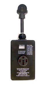
50-amp Surge Protector from Progressive Industries

A 50-amp portable surge protector from Progressive Industries

In the images above, we can see two portable surge protectors. Portable units have the advantage of being able to be readily moved from one RV to another. This makes for a zero installation setup with no rewiring. Just plug it into the campground pedestal and plug the RV’s power cord into the surge protector. The disadvantages are that it is out in the weather and could get stolen or vandalized. There are locking kits available to lock them to the pedestal but then you are trading the convenience of not having the initial install versus connecting it and securing it to the pedestal every time you go camping. If the pedestal’s receptacle is very low to the ground it’s possible that the portable unit may not fit because of the right angle plug and the bulk of the unit that needs to hang down from the outlet. One last caveat is that the hard wired units sometimes offer a remote display option so that you can monitor the incoming power from inside the coach. With a portable unit you won’t be able to utilize that option. The actual protection levels of the portable units are generally the same as their counterparts in the hard-wired segment so there’s no advantage or disadvantage there.
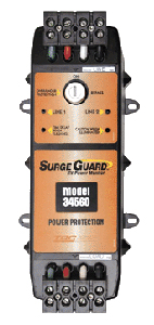
Surge Guard 50-amp hardwired surge protector
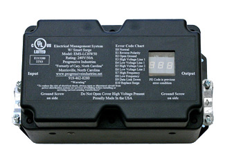
Surge Guard 50-amp hardwired surge protector

50-amp Surge Protector from Progressive Industries

A 50-amp Surge Protector from Progressive Industries

Hard-wired devices do take a bit of installation labor but it’s not that difficult. You simply mount the unit in the same electrical compartment that your RV’s cord is located in. Remove the power cord from the transfer switch and connect the cord to the surge protector’s input terminals. Then run a short whip cord from the surge protector’s output to the transfer switch and you’re all set. Some RV owners choose to just cut 2-3′ off the end of the power cord while some choose to buy another short chunk of cord from a home improvement store. If you have a power cord reel you’ll undoubtedly be buying a new whip. If your surge protector includes a remote display you will have to find a location for that display, mount it, and then connect it with a standard RJ11 modular phone cable. A cable is generally supplied but if you want to run a longer distance you may have to make a new, longer cable to reach the remote display panel.

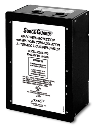
Surges are rated in Joules. The bigger the surge, the higher the number, so you want to get a surge protector with the highest possible rating. The popular Surge Guard 34560 is rated to handle up to 1,750 Joules of power surge. It will shut down power to the coach if the voltage falls below 102 Volts or is higher than 132 Volts. Various LEDs will inform you whether the receptacle is properly wired or has a bad ground, reversed polarity, or open neutral. If it shuts down the power due to low or high voltage or an open neutral wire it will reset itself once the power returns to within tolerances. There will be a two minute, 15 second delay before power is re-energized though to allow any air conditioners time to bleed off their head pressure. If you decide that you want to bypass the voltage cutouts feature and allow power through you can defeat the unit by turning a key switch. In this mode you will still have surge suppression, however. Surge Guard also makes automatic transfer switches with built in surge protection and low voltage protection. These transfer switches are becoming very popular in recent diesel pushers due to their ability to also communicate with a multiplexed network control panel.

The Progressive EMS-HW50C is the gold standard of surge protectors. It’s rated to handle up to 3,560 Joules of surge. Low voltage cutoff occurs at 104 Volts and high voltage cutoff occurs at 132 Volts. It comes with a remote LED display that is very easy to read. In addition to displaying the incoming voltage of both poles it will also display the amperage draw on each pole as well as the frequency in Hertz. If any pedestal mis-wiring is present or any shutdown has occurred the LED display will display a 2 digit trouble code that defines the problem according to the chart that is printed on the unit as well as in the owner’s manual. The remote display can be mounted inside the coach or in the basement compartment. In this way it’s handy to locate the EMS-HW50C near the back of the compartment where it’s easy to wire and still have the remote display located near the front of the compartment where it is easy to view. The bright LED is easy to read in bright sunlight and a bypass switch is located on the remote display to bypass the power shutdown function, just like in the Surge Guard above. You have the choice of selecting either a 15 second power-on delay or a 136 second delay. Most modern air conditioners have a built in two minute restart delay so 15 seconds is the normal selection. You can also buy a second remote display that allows you to mount one in the basement and one inside the coach if you desire.

While the EMS-HW50C is the old standard, Progressive Industries also make the EMS-LCHW50 surge protector. The “LC” stands for Liquid Crystal display. Instead of a remote LED display, the LC series uses an integral liquid crystal display that is located right in the cover of the unit. The protection level is the same as its big brother but, depending on where the unit is mounted, you may have more problems in viewing the display. LCD screens just aren’t as bright as LEDs and dark places and bright places are not their friends. Coupled with the fact that the remote LED display can be located anywhere and the LED holds a huge advantage. Still, the LC series does hold a $50 price advantage over its more costly brother.
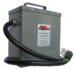
Hughes Autoformer

The Hughes Autoformer will boost low voltage

Once your surge protector determines that the campground voltage is below the minimum acceptable level it shuts down power to your coach. If you really want to power your coach you have some decisions to make. You can go turn the key or flip the switch to bypass your surge protector’s low voltage cutoff feature. You have to wonder if that’s a very safe thing to do though. After all, the reason it shut down is to protect your coach from low voltage. Remember that wattage is true power and volts times amps equal watts. If a device in your coach needs a certain amount of watts and the voltage falls, the amperage will rise and those excess amps will overheat and damage your circuitry. Another option is to run your generator. That may or may not be desirable, depending on your environment and neighbors. You can always wait it out in case it returns once the sun goes down and everyone’s air conditioner stops running non-stop. Or, you can get an Autoformer.

An Autoformer is a voltage booster. While they do offer some surge protection, it’s main claim to fame is it’s boost technology. An Autoformer will automatically boost the incoming voltage. Models such as the Hughes Autoformer RV 450 will boost the voltage 5-10-15% as needed. That gives you the ability to take an incoming voltage as low as 91-92 volts and boost it to the minimum 104-105 volt cutoff that the surge protector needs to see. If used in conjunction with a surge protector the Autoformer is always mounted first so that it boosts the voltage prior to the surge protector. If it was mounted after the surge protector it wouldn’t work because it would kill any input voltage to the Autoformer and the Autoformer needs to see something before it can boost anything. The Autoformer is an optional piece of equipment. If you don’t feel that it’s that critical that your coach have power at all times or if you camp at nice RV resorts that have clean power you may not feel it is necessary. If you have a coach with a residential fridge and happen to encounter low pedestal voltage frequently then it may be a life saver that will save you from having to run your generator frequently. The Autoformer doesn’t get very hot and it can usually be mounted in the same compartment as the surge protector and power cord reel. In that case a hard-wiring kit is available that lets you splice into the cord reel’s output whip so that it can be inserted into the power cord whenever necessary. This keeps it safe and dry rather than sitting next to the pedestal exposed to the elements and potential theft or vandalism.

That’s it for this month. This is third and final installment of this series. I hope I didn’t bore you too much. Hopefully you’ve gained enough knowledge about how your motorhome’s electrical system operates. Now – go out and buy that multimeter if you don’t have one.

National Indoor RV Centers blogger Mark Quasius profile picture

Mark Quasius is the founder of RVtechMag.com, the past Midwest editor of RV Magazine, writes for numerous RV-related publications and a regular Contributor to FMCA’s Family RVing Magazine. Mark and his wife Leann travel in their 2016 Entegra Cornerstone.

NIRVC Angie: 10 Things You Want To Know!

NIRVC’s Angie Sieverts Morell is a fascinating woman.

In the span of a dozen years, she has transformed from a busy stay-at-home wife & Mom to three children, to the award-winning National Sales Director for National Indoor RV Centers, and NIRVC’s YouTube Superstar.

Many of us first encountered Angie as the dynamic spokesperson for NIRVC on YouTube. Whether you were searching for a brand-new or used luxury motorhome, looking for information or a walk-thru of a certain brand or model, or trying to learn how to RV in general…

There she was, with all the details and technical information, answers and reassurances to your RV questions and concerns. Always fresh and personable, exquisitely dressed, often in a skirt and heels – explaining power systems, diesel engines, chassis details, motorhome tire protection and fire safety.

When we first bought our 2016 Entegra Aspire 40P (from another dealer, not knowing about NIRVC at the time), we quickly discovered Angie on YouTube and in our Entegra Owners Facebook Group.

Honestly, her terrific four-part series of RV 101 beginner videos on YouTube got us on the road to living, working, and traveling full-time around the country in our new-to-us motorhome.

(As an aside: Two years later, I still use Angie’s super-easy & quick Instant Pot Shredded Pork recipe from Part 2 of the series for Travel Days! I wrote it down as best I could from the video. As an added bonus, Angie sent me the actual recipe, which I’ve included below. Enjoy!)

I have to admit, when we finally met Angie IRL – In Real Life – at the Florida RV SuperShow in Tampa, my husband and I were both starstruck and so thrilled to meet
NIRVC Angie! She is just as lovely, super smart, fun and genuine in person.

We then spent two weeks with Angie & NIRVC at the AIM Club Rally: California Dreamin’ in San Diego, and the FMCA International Convention & RV Expo in Tucson, Arizona.

We saw her frequently at both events: Going, going, going, 9am to 9pm (and working much earlier and later on text, email and follow-ups, I’m sure) – always looking great, full of energy.

NIRVC Angie & Sherri at FMCA Tucson – March 2022

I had the great pleasure of “going to work with Angie” on the last morning of the FMCA Tucson event. We had a chance to sit down for a few minutes, so I could interview her for this article. To ask All The Questions…

NIRVC Angie: 10 Things You Want To Know!

#1 – How does she do it?

As NIRVC’s National Sales Director, coordinating five locations across the U.S., attending NIRVC events, including AIM Club Rallies, Brand, and other RV association events, and keeping up with the industry, producing videos…

Angie travels. A lot.

She typically travels (by airplane– it’s a lot faster!) three weeks out of every month, and enjoys one week at home in Texas.

(I still don’t know how she does it!)

#2 – RV Life & Family Time

Fortunately, NIRVC locations and travel coordinate with family time on occasion, with her three kids, all grown up and living in different states: Tennessee, Utah, and North Carolina.

In fact, when I talked with her recently, she was “working out of Nashville,” and enjoying time with her brand-new grandbaby (May 2022), with her son, Sam, and his wife, Aubrey, a singer/songwriter, at their home in Nashville.

Angie’s youngest daughter, Shea, recently graduated from college in Utah. Shea is staying in Utah, launching her career in marketing with an innovative women’s health and supplement company. (Shea sounds a lot like her mama, with her ambition and enthusiasm.)

Angie’s daughter, Madison, and her husband, Austin Corbett, currently live in North Carolina, with Angie’s first grandson, now 18 months old. (They are expecting a little sister, due in September!)

We talked about the convenience of RV travel and grandparenting, as a means of keeping up with adult children and grandbabies. When you can visit and spend time with grandchildren and their parents, with everybody still having their own space: Win/Win.

While Angie and her husband, Mark, are not quite on the grandparent caravan yet (with plenty of access to beautiful RVs, but no time to travel in them), they are excited about eventually having more time for RV travel, for grandparenting, and for tailgating(?!). Not only is Mark an avid fan of college football…

Angie & Mark both look forward to tailgating in the future, following Madison’s husband in his career with the NFL. They were thrilled when Austin played for the L.A. Rams in SuperBowl LVI this year (they won!), along with the entire NIRVC family and cheering squad. Austin went to the Carolina Panthers after the SuperBowl victory.

Lots of tailgating (and grandparenting) ahead!

#3 – Angie’s RV Background?

Like many of us: None. (Look at her now!)

In the early 2000’s, Angie was a busy stay-at-home mom with three young children. She was active in her family, schools, community and church. She found time for “little” outside projects, like interior design and staging homes for sale for local real estate agents. She also loved running, for physical fitness and activity.

Brett Davis was a neighbor, family friend, and fellow church member, her son’s scoutmaster. Back in the day, Angie and Brett were in a running group together, and ended up as running partners, out early every morning.

On their early morning runs, her neighbor, friend, and running partner started thinking aloud, sharing his Big Idea and plans: RVs, indoor storage and service, and his vision of customer service.

It wasn’t long before Angie got pulled in–

#4 – Indoor RV Storage???

By 2009, Brett had an enormous, empty building in Lewisville, Texas. Angie found herself helping out: marketing, advertising, and selling storage space.

“Trolling the boat docks,” as she says, to sign up storage customers – any type of large storage – to fill Brett’s huge, empty building. (The very first National Indoor RV Center facility, outside of Dallas.)

#5 – From Selling Storage to Staging RV Interiors

Five years later, the Lewisville storage was full of big, beautiful motorhomes. The second indoor storage facility was built and opened in Lawrenceville, Georgia, just outside of Atlanta.

NIRVC started selling RVs – a partial line of Newmars.

As it turns out (I didn’t realize – wow!), selling different brands of recreational vehicles and luxury motorhomes – RV dealership – is a very competitive and complicated business, with licensing locks and territory restrictions. What you’re allowed to show and sell, where…

That’s all to say, in 2014, Brett started selling RVs and asked Angie to use her interior design skills and experience to stage brand-new motorhomes for sale, in Dallas & Atlanta. The traveling begins…

*OG noun \ ō-ˈjē \
Slang – originally a gang term for “original gangster”
Now defined by www.merriam-webster.com/dictionary/OG as:
: someone or something that is an original or originator and especially one that is highly respected or regarded.

Early in 2015, at a sales training meeting, Brett Davis overheard a salesman refer to a client as a “50-pounder,” meaning a sale where the salesman had made more than $50K in commission.

Brett was horrified at common sales tactics in the industry, realizing that these were the very things that resulted in salesmen “ducking and hiding” from those same customers in the future, after the customer felt ripped off or taken advantage of.

Brett started NIRVC with a strong business ethic and customer service commitment to make “Customers for life.” He had visions and ideas from the beginning about rallies and “homecoming” events where customers would come back to NIRVC, as a family, for all of their RV needs: education & community, maintenance & service, storage, trade-ins and future sales.

He believed then, and now: “It’s much easier to teach someone product than character.”

So he fired the entire sales staff, and convinced Angie to “try” sales.

Of course, she was a natural. Within two years, she was earning industry awards from brand manufacturers and chassis makers for breaking sales records.

It wasn’t easy, at the time, for a woman to break through in the traditionally male-dominated RV industry. Angie recalls the “Big Freeze” from male sales reps at the manufacturers. She credits Entegra’s Ted Cook with always answering the phone and helping her work through questions to build product knowledge.

Angie truly is NIRVC’s ‘OG’ RV Lifestyle Specialist (designated job title for sales at NIRVC).

The NIRVC approach to sales and service is entirely the opposite of what happens at typical auto and RV dealerships. Instead of predatory tactics and making the sale (with expensive add-ons) at all costs, NIRVC is focused on customer service, listening to their clients, building relationships, and earning customers – and friends – for life.

#6 – NIRVC Family – Myths & Legends

“Did you sell your first RV to Tommy & Bonnie Townsend?”

(I never know what to believe with Tommy Townsend, the President of NIRVC-sponsored AIM (All-Inclusive Motorhome) Club! Tommy has a fantastic and mischievous sense of humor, as well as a big heart and willingness to help anybody and everybody, anytime.)

Angie laughed and didn’t actually answer directly. (So it may or may not be true?)

She did tell me about NIRVC’s very first Entegra Rally in May 2015, after she had just started selling motorhomes. NIRVC stepped in as sponsor to the event when another RV dealer backed out unexpectedly. It was held at the Buckhorn Resort in Kerrville, Texas.

Angie met Tommy & Bonnie at that event. The Townsends have been friends, Angie’s support team, and practically family, ever since.

Angie fondly recalls a core group of at least a dozen RVers-who-became-friends at that first Entegra Rally. And how, through subsequent sales and referrals, those long-term relationships served as a foundation for her career.

#7 – NIRVC National Sales Director

Obviously, with her success (and growing YouTube fame ;-), NIRVC needed to clone Angies, to keep up with demand.

As NIRVC’s National Sales Director, Angie has done just that. She travels and works closely with her team of 50 RV Lifestyle Specialists over the 5 NIRVC locations.

Her role now is to instill in them her own (and NIRVC’s) work ethic and customer service philosophy:

  • Success is built on relationships, communication, and product knowledge.
  • Focus on taking care of the customer for life.

It is refreshing to talk with Angie and hear her genuine love and respect for customers – her friends & family. She appreciates every customer, and whatever they’re spending to follow their dream. Whether they’re looking for an economical Class B campervan or a million-dollar Class A luxury motorhome, NIRVC Lifestyle Specialists are going to make the most of the experience for the customer.

As Brett Davis says: “With Angie, you don’t become a customer. You become a friend.”

#8 – NIRVC YouTube SuperStar

We have to step back a bit, to 2014, to talk about YouTube.

When Brett brought the idea up, none of the salespeople at the time wanted to do it. Angie was willing to step up.

With “zero” experience or training in video, completely unscripted, she jumped right in.

Angie has produced model year demo and walk-thru videos since 2015: Entegra, Newmar, Winnebago, Jayco and many others. Every year.

Beyond the annual new model demos, which are impressive, she produces factory tours, basic maintenance, RV safety and new product & accessory videos.

NIRVC has 64.4K Subscribers and 141 Videos on their YouTube Channel.

While Angie hasn’t starred in all of those videos, you can bet most of those subscribers know and love NIRVC Angie.

She is amazing: knowledgeable, technical on every aspect, inside and out. She talks as much about operational and maintenance details as she discusses decor and interior amenities. Never boring.

Always put-together: hair, make-up, jewelry and heels, well-dressed, usually in a beautiful dress, unless she’s doing a very technical video (like the RVing 101 series: packing, driving, setting up and breaking down camp – all on her own).

I can’t remember exactly when Angie came into our lives via Youtube. My husband, the RV researcher, found her first, before I realized what was ahead of us: Full time RV travel. What?!

He wisely won me over to the idea by showing Angie videos: Her walk-thru of the 2016 Entegra Aspire 44B. Those incredible RVing 101 videos.

BONUS – Pulled Pork Recipe!

 #9 – What are you most proud of, in your career with NIRVC?

  • Overcoming and breaking through in the male-dominated industry.
  • Seeing and helping more women achieve success in the industry.

#10 – What are your plans for the future?

“Stay with NIRVC, a company I truly believe in, with a job I love that doesn’t feel like work. Lots of fun and exciting things ahead with NIRVC!”

While we were talking in a corner of the NIRVC tent that day, a confetti cannon went off just outside, gently showering the area with fluttering strips of brightly-colored paper. This is how NIRVC celebrates a new RV buyer at the FMCA Rally, with all appropriate excitement and fanfare.

Angie excused herself and ran over to celebrate and welcome her new best friends into the NIRVC family.

National Indoor RV Centers blogger Sherri Caldwell profile image

Sherri Caldwell is the founder of BooksAndTravelUSA.com – Full-time RV Travel Blog & Book Club/U.S. Literacy Project. With her husband, Russ, she is currently living, working, and traveling full-time in their 2016 Entegra Aspire: Charlie-The-Unicorn RV.

RV Electricity 101 – Part 2 An RV Owner’s Guide to RV Electrical Systems

Last month we began our tutorial on RV electricity explaining the basics of electricity (the boring part), how the electrical panels are configured and briefly touched on generators. This month is part two of a three-part series and we’ll get a bit more interesting as we help you understand batteries, transfer switches and inverters. Finally, we’ll conclude this series next month with the final installment that will cover more advanced topics such as solar power, surge protection and energy management systems.

Transfer Switches

Sometimes the 120 volt devices in your motorhome need to be powered when you are not plugged into a campground pedestal, frequently referred to as shore power. When shore power is unavailable, the on-board generator set can be used to power these devices. Generators can be used in a number of situations, such as camping in remote areas where access to power is not available. A number of systems, such as lighting, water pumps and fans, are powered by your 12 volt battery. However, there will come a time when these batteries need to be recharged. The on-board generator can be used to power the coach’s battery charging system in the absence of shore power. Another use for generators is to power the rooftop air conditioners to make for a more comfortable motorhome interior in hot weather.

Your RV’s 120 volt electrical system is fed through a central distribution panel where all of the circuit breakers are located. In order to power this panel from two different power sources we can choose one of two methods. The first is the more cost effective and least costly and is commonly used in lower cost travel trailers. That method entails hard wiring a power cord to the breaker panel’s inputs. When not plugged into shore power this cord can be plugged into a generator set outlet to provide power to the RV’s electrical systems. While this method is inexpensive, it’s less convenient because you have to physically switch the plug from the shore power receptacle to the generator receptacle. The second method is to install an automatic transfer switch.

Automatic Transfer Switch

Automatic Transfer Switch

A transfer switch is basically a three way switch that switches between two inputs and connects them to a single common output. An automatic transfer switch mounted in a motorhome is located prior to the breaker panel where it can intercept the shore power cord feed to the breaker panel. The output of the transfer switch then goes to the main breaker of the breaker panel. The shore power cord is connected to one of the inputs in the transfer switch while the output from the generator is hard wired to the transfer switch’s second input. Transfer switches will connect one of these two inputs to the switch’s output. Manual transfer switches need to be manually switched by moving the switch lever on the box and are uncommon in a motorized RV. Automatic transfer switches commonly used in an RV will do this automatically and are logic controlled to switch under a given set of conditions. Generally automatic transfer switches will default to the generator inputs and are mechanically held. Once shore power is present the magnetic coils will pull the switch’s contact relays over to the shore power side. This is why you typically hear that clunk when the switch engages shortly after connecting to shore power. As soon as the shore power is no longer present the switch will revert back to its generator priority position.

Automatic transfer switches contain relays that switch between the two power sources. The magnetic coils that activate the relay contacts are engaged when the circuitry detects the presence of shore power. If you are running as large load the current across these contacts is substantial. When shore power is connected or disconnected, a large arc can occur across the contacts. Eventually this can pit the contacts and cause them to weld shut, rendering the transfer switch inoperative. If you have large loads operating it’s a best practice to switch them off before disconnecting from shore power to prevent this from happening. If your contacts do pit it is possible to file them clean by shutting off all power sources to the transfer switch, removing the cover and filing the contacts with some 120 or 220 grit sandpaper to clean them up. If they are too far gone the switch will need to be replaced or repaired. Another point of maintenance is to inspect the lug connections where the wires connect to the switch. The Allen head screws can loosen up over time, allowing loose wiring connections that can cause arcing in the connectors. It’s a good practice to inspect these connections every year or so and tighten them if necessary.

Generators

A motorhome has wheels, which means it’s mobile and doesn’t have to stay in one place forever. This means that shore power isn’t always available. Fortunately, most motorhomes are equipped with an on-board generator set to provide AC power when you are driving or when camping in a location that has no shore power. On some units you’ll find this generator in a basement compartment designed to provide adequate ventilation, intake air for the engine and a way to get rid of exhaust fumes. If you have a diesel pusher motorhome the odds are that your generator will be mounted in the very front of the coach, usually on a slide-out mechanism for ease of service. Permanently mounted generators are larger, heavier and quieter than their smaller portable cousins.

An Onan gasoline powered generator.

Onan gasoline powered generator

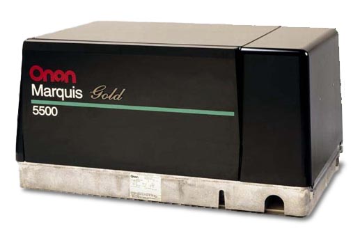
Gasoline powered Class A motorhomes will be equipped with a generator powered by a gasoline engine. The generator shares the same fuel tank as the vehicle engine but uses a separate fuel pickup within that tank. Usually these pickup tubes are cut short so that the generator will not run if the fuel level gets below a ¼ tank but this amount can vary from one manufacturer to the next. The reason for this is so that you can’t totally drain your fuel tank while dry camping. The ¼ tank remainder ensures that you will always be able to start your RV’s engine and drive to a refueling location. These generator sets are designed to slide into a basement compartment that is designed for that purpose so access to the controls and engine service points is done through the removable side cover on the generator, which also serves to contain the cooling airflow and add additional sound deadening capability.

Onan Quiet Power diesel generator

Onan Quiet Power diesel generator

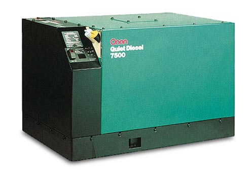
Diesel powered generators can be found on motorhomes that are powered by diesel engines. Some of the entry level class A diesels are really front engine gasoline chassis with a diesel engine in place of a gasoline engine. Also, many smaller B+ and Super C motorhomes are now being made with small diesel engines. In this case the diesel powered generator will be fairly small (in the 4 KW to 7 KW range) and will be mounted in a side compartment in the same fashion as the gasoline powered generators. On a rear engine diesel pusher, the front of the coach is clear of engines and radiators. In this case you’ll find a diesel powered generator that is mounted in the front cap on a set of slide rails. The generator can be slid forward out of the coach to allow better access for servicing the unit. These units generally start at around 7,500 watts and run up to 10,000 or 12,500 watts in size. Some older motorhomes used a propane powered generator that ran off the RV’s on-board LP tank. However, these are rare and less desirable because the limited capacity of the propane tank didn’t give the generator a very long running time before the LP tank was empty. Used coaches with propane powered generators are very hard to sell and their resale value reflects this.

Generators that are rated up through 8,000 watts are usually single pole 120 volt-only generators, referred to as “in-phase” generators because both windings are in the same phase. Larger generators, 10,000 watts and up are two pole split-phase 120/240 volt generators with a center tap neutral. Because motorhomes rarely have any 240 volt appliances you may think that this arrangement isn’t needed. But if you refer back to our split phase 120/240 diagram you’ll recall that each phase has a given amount of amps available. That’s what allows you to balance your load and eliminate the heavy wiring required for a 10KW generator, which would output 83.33 amps if it was an in-phase design. Note that a 50 amp electrical service is equivalent to 12,000 watts, which is the size generator required if you needed to supply a full 50 amps to your RV’s breaker panel.

Frequency and RPM

Earlier we saw a graph of the AC and DC waveforms. The vertical height of the waveform represented voltage. But we also need to control just how fast this electrical pulse occurs. This is plotted horizontally on the graph and is referred to as frequency, which is labeled as Hertz. In North America all electrical power is 60Hz while in Europe and most of the rest of the world electrical power runs at 50 Hz. Hz is basically a counter of how many electrical pulses or waves occur in one second. A small portable generator must run at 3,600 RPM in order to produce 60 Hz of electrical power. When you divide 3,600 revolutions per minute (RPM) by 60 seconds we get 60 revolutions per second. It takes two field coils, a north pole and a south pole, to create the magnetic field necessary to create electricity. There are two field coils in a small portable generator, so it takes one revolution of the generator to create one Hertz. When the generator is turning at 3,600 RPM it will produce 60 Hz. It doesn’t matter what size output the generator makes but the speed at which it turns is important.

Small portable generators tend to be noisy because an engine running at 3,600 RPM isn’t very quiet. They were designed to be light and portable. In a motorhome this isn’t important because the generator doesn’t need to be lifted because it will be mounted into the RV. What is important is the noise level. If we add a second set of field coils to our generator, we will double the frequency to 120 Hz when running at 3,600 RPM, which isn’t good and will burn up our electrical devices. But if we take that same 4 pole generator and slow it down to 1,800 RPM we will still have 60 Hz. It’s just that we are passing twice as many magnets during the same revolution so by reducing the number of revolutions by half we will still maintain 60 Hz. This is the way many RV generators are set up. The 1,800 RPM speed of the engine allows for quieter operation. Because we don’t have to lift this generator we can also add a nice large muffler to it. The big drawback is that we have to use a larger engine. A small 8 HP engine is capable of creating 3,500 watts at 3,600 RPM but when you slow it down to 1,800 RPM it will only put out around 5 HP, which isn’t enough. By going with a 12-14 HP engine, we will still have 8 HP available at 1,800 RPM to then make our 3,500 watts of power. This means that the engine will be physically larger, weigh more, be quieter and more durable, and cost more than a smaller engine that is running higher revs. But the gains are well worth it in an RV application. Large utility power plants carry this even further and can use as many as 24 field coils in their generation systems so that they only have to turn 300 RPM. Less RPMs means greater life but more weight and size, while less magnets means less weight and size but greater speed and wear.

There is one exception to this RPM rule for generators. There is a trend towards inverter generators which use a variable speed engine to produce DC current to an inverter board within the generator. The inverter will convert DC power to AC power electronically. A DC generator is not sensitive to its RPM because the inverter controls the frequency and voltage electronically. These are smaller generators, such as the Onan Quiet Diesel (only up through 8KW) and small portables such as the Honda EU series. The benefit to this is that the generator can run at a lower speed when the demand for power is light, ramping up to higher speeds as the demand increases. This will minimize fuel consumption and supposedly reduce the noise level, although some models can actually be louder at full song compared to a traditional 4-pole generator. The electronic circuitry of the inverter will regulate the output voltage at a steady 120 volts and the frequency at a consistent 60 Hz.

Effects of Altitude

Any engine will produce a given amount of power based upon how much fuel and air it consumes, and higher power loads and RPMs consume more fuel. Because fuel and air are in a somewhat constant ratio, the engine will require more air at higher power outputs. But as we drive our motorhomes up into higher elevations, the air gets thinner and the engine loses its ability to produce its maximum rated power. This results in a corresponding drop in generator output wattage.

high-altitude image of a Suncruiser at 11,000

High-altitude image of a Suncruiser at 11,000 feet

 Different engines will react in varying amounts. For instance, the output wattage of the Onan Marquis Gold series of gasoline powered generators will lose 3.5% for every 1,000′ in altitude gain over 3,000′. The Onan Quiet Power Diesel 10,000 watt will derate 3.5% for every 1,000′ over 500′ and it further derates by 1% for every 10° F increase in temperature over 85° F. A good rule of thumb for most gensets is that you will lose 10% of the rated output every time you gain 3,000′ in altitude. This means that a 7,500 watt generator running at 9,000′ of altitude will only be capable of producing a bit over 5,000 watts at that altitude.

Diesel engines are pretty well able to handle the fuel injection requirements at higher altitudes but carbureted gasoline powered engines do not have that luxury. The Onan Marquis Gold series of generators uses carburetors that have an altitude compensation adjustment on the carburetor. By dialing in a higher altitude you will lean out the mixture to prevent spark plug fouling and excessive smoke. It is very important that you also dial it back when descending to lower altitudes or else the engine will run lean and you can burn the engine’s valves.

Breaker Panels

Breaker panels serve two functions. They provide a central distribution center for all of the various circuits to tie into the incoming power supply, and they also provide overload protection to prevent electrical fires from any short circuits. Fuses are pretty much a thing of the past on high voltage circuits in RVs, so resettable circuit breakers are provided in their place. Breaker panels, also called power distribution centers, are mounted in an accessible location inside the RV so that the circuit breakers can be reset as needed. They are also used to de-energize a given circuit so that circuit can be safely worked upon without endangering the operator.

A 30 amp in-phase circuit breaker panel

A 30 amp in-phase breaker panel

Circuit breaker panels are going to vary quite a bit from one brand to the next as well as between a 30 amp and a 50 amp service. A 30 amp service will be single pole 120 volts so it will have 3 wires feeding it – a black hot wire, a white neutral wire, and a green or bare copper ground wire. Because it’s a single pole service, all of the breakers will be fed by the same common hot wire.

A 50 amp split-phase circuit breaker panel

A 50 amp split-phase breaker panel

A 50 amp service will be different because it’s a two pole split phase service with two hot wires. In this case the black wire will be referred to as L1 while the second hot phase will be a red wire and referred to as L2. In this instance the breaker panel will have two main lug inputs and a divided buss that sends L1 to half of the breakers while sending L2 to the other half. In either situation there will be a main breaker that controls power to the entire distribution panel. It will either be a single pole 30 amp breaker or a two pole 50 amp breaker, depending upon which service your motorhome is equipped with.

In addition to the main breaker there will be a number of output breakers – one for each circuit in the coach. Any given circuit may contain multiple outlets, but that particular breaker will control every outlet on its circuit. So if a device that is plugged into an outlet causes the circuit breaker to trip, that entire circuit will be dead. Some of the panels used in motorhomes are fairly small so that they don’t take up too much room, which is somewhat limited in an RV. However, there may not be enough available slots for the number of circuits that are needed. Split circuit breakers are commonly used in this application to solve this problem. A split breaker places two half width breakers into one common unit that snaps into a single breaker panel slot. This gives you the ability to run twice as many circuits as normal circuit breakers. Of course, you still need to find enough room inside the box to stuff all of that wire so that may be the limiting factor.

Sub-Panels

Normally, all of the circuits can be powered from the one breaker panel. Many motorhomes are now coming with more complex electrical systems and are using inverters to power certain devices. We’ll talk more about inverters in a later chapter, but for now let’s just say that inverters use battery power to produce 120 volt AC power. Inverters are also fed 120 volt AC power from the breaker panel. They have an internal transfer switch that passes the shore power through rather than using the batteries to produce power. It will pass this power through whenever it is available or invert it from the batteries when it is not. This means that any devices that need to be powered from the inverter need to somehow be connected to its output. They still require some sort of overload protection so many of the larger inverters send their output, or the pass through power, to a sub-panel. This sub-panel will act as a distribution point for all of the circuits that are desired to be run off the inverter. It will have a few circuit breakers in it to protect these circuits from any overloads. The inverter itself will receive power from either one or two circuit breakers in the main panel. In this way all of the AC power from the main breaker panel will pass through the inverter and into the sub-panel, where it can be distributed to the desired circuits. Many of the larger inverters also serve as battery chargers, so whenever shore power or generator power is present it will charge the batteries in addition to operating in the pass-through mode.

Iota integrated breaker panel

Iota integrated breaker panel

This requires the installation of a second panel. Adding a sub-panel to an RV does take up valuable space, which isn’t always that easy to do. Some breaker panels, such as the Iota IDP-240B, offer an integral sub-panel. By splitting the buss inside the panel, a portion of that box can be used for sub-panel circuits if the inverter is wired to return power to that portion of the buss bars. This offers a huge advantage when trying to fit a breaker panel into an RV without tying up valuable space. The Iota is a compact breaker panel with an attractive cover with a smoked glass cover over the breakers. If a breaker trips, an LED can be configured to illuminate, which identifies the circuit as tripped without requiring removal of the cover. It can be configured with the split buss design so a separate inverter fed sub-panel is not necessary.

Batteries and Chargers

Batteries are critical to an RV. They start the engine and provide power to run accessories when driving. When parked they provide power to run lighting, water pumps, and various other 12 volt accessories. They can even be used to power an inverter to provide 120 volt AC power. Because of their heavy use they can sometimes be a source of aggravation and maintenance. Let’s take a closer look at batteries, how they work, and how to properly care for them. We’ll also delve into battery chargers and charging methods.

The battery compartment from an Allegro Bus

The battery compartment from an Allegro Bus

A single battery may be fine to operate your passenger car but it’s just not enough power to handle the more advanced requirement of an RV. To do this, multiple batteries are arranged together into a battery bank. There are two types of batteries and each type has a different intended use. Automotive batteries are what you have in your car. They are designed to output a large burst of amperage to start the vehicle, then slowly recharge from the vehicle’s alternator. The key here is that they dump a lot of amperage in a short time, then rest for a while slowly getting recharged. Most diesel motorhomes will have two engine-starting or chassis batteries in order to crank these larger engines.

When camping, your coach electrical systems operate quite differently. They will draw fewer amps than a starter motor but they will do that over a longer period of time. For this application deep cycle batteries are used. Deep cycle batteries are designed for maximum performance by slowly draining amps from them and sustaining this draw over a longer period of time. Most coaches will have four deep cycle batteries in a battery bank to ensure that there is enough capacity to supply adequate power over a longer length of time. This can vary and some smaller coaches may only have two, while larger coaches may have as many as eight batteries in a bank.

RV electrical systems are 12 volt systems. Whenever you connect multiple batteries together you have to make the proper connections in order to maintain 12 volts. If batteries are connected in parallel they will retain their voltage, but if they are connected in series the voltages will add up. So, if you have a bunch of 12 volt batteries that you want to connect into a battery bank, you simply connect all of the positive and negative posts together to give you increased load capacity or amp-hours. But many RVs are using 6 volt batteries for their deep cycler applications, which are commonly used in golf cart applications. They have a heavier plate design and are more durable, plus they output more power than a 12 volt battery of similar dimensions. The only downside is that you need to connect them properly to get a 12 volt output. Basically, you connect a pair of 6 volt batteries together in series to give you a single 12 volt battery. Then you connect the positive posts of this pair together with all of the other pairs and then do the same with the negatives. The following diagrams show a four battery bank of both 12 volt and 6 volt batteries and will help explain this better.

diagram of series versus parallel battery connections

diagram of series versus parallel battery connections

Battery Types

Batteries come in different types. For RV applications the most common are flooded batteries or AGM batteries. Flooded batteries are filled with electrolyte. This electrolyte is a diluted form of sulfuric acid. When a load is placed on the battery, the acid puts a charge on the lead plates and creates electricity. At this time some of the sulfur and oxygen leaves the acid and forms a sulfate on the lead battery plates, leaving water as the remainder. If a battery is totally discharged, the battery plates will be coated with sulfate and the electrolyte will be mostly water, which is why dead batteries can freeze in cold temperatures but fully charged batteries will not freeze. When the battery is recharged, the sulfate falls of the battery plates and recombines with the water to change it back to acid again. If the battery is overcharged (in other words excess voltage is applied to it when it already is charged up), the water can boil out of the battery and acidic vapors can leave via the vented battery caps. This reduces the water level and if it gets below the battery plates it can harm the battery. It also tends to corrode the battery connections because of the acidic vapors. Maintaining the proper water level is critical to good battery performance.

AGM batteries use electrolyte but not in a liquid form like flooded batteries. The acidic electrolyte is absorbed into glass fiber mats that are wrapped around the lead battery plates. With AGM batteries there is no need to ever worry about adding water because there is no water in them so maintenance is greatly reduced. The battery terminals also are not as susceptible to corrosion as flooded batteries because there is only microscopic outgassing, or venting, of electrolyte vapors. The outgassing of flooded batteries means they need to be in a vented compartment and clear of anything that could create a spark. AGM batteries can be located anywhere because they truly are sealed. AGM batteries are typically used in aircraft and they can be used in any orientation, even upside down, with no negative consequences. AGM batteries also offer greater performance over a comparable flooded battery because the voltage drop curve is flatter.

Voltage State of Charge
12.6+ 100%
12.5 90%
12.42 80%
12.32 70%
12.20 60%
12.06 50%
11.9 40%
11.75 30%
11.58 20%
11.31 10%
10.5 0%

Battery Charge Voltages

A fully charged battery will test out at 12.6 volts. This is “at rest” voltage. When a battery is being charged, the alternator or battery charger will put out higher voltage, sometimes as high as 14.5 volts. Immediately after stopping the engine or switching off the battery charger, the battery will have a false surface charge which is meaningless and probably in the mid-13 volt range. Leave it rest for a while (at least 15 minutes or as long as an hour or two) before testing. This will allow the battery to rest and lose its surface charge. A slight load will help shorten that time somewhat. You can continue to draw current from the battery until the at-rest voltage drops below 11.9 volts. At that point only 40% of the battery capacity remains. In other words, you’ve used 60 amps from a 100 amp battery. If you continue to use the battery below this point you can get current from it, but the voltage will be low and that won’t do your electrical equipment any favors. You will also drastically shorten the battery’s life.

Batteries are not really rated in years of life. A battery is typically rated at 50 cycles of discharge and recharge. In other words you can totally discharge the battery, then recharge it. That’s one cycle. Do that 50 times and the battery will be shot. The level at which you discharge isn’t linear, it’s graded on a curve. So, if you only drain the battery halfway and then recharge it you won’t double your life to 100 cycles. It’s more like 200 or more. Similarly, if you only drain your battery to 75% you won’t quadruple your battery’s lifetime to 400 cycles. It’s more like 1,200 cycles. It is to your advantage to keep your battery bank from getting too low by frequently recharging it.

If you were to plot battery voltage vertically on a graph against battery consumption horizontally on that graph, you would see that the voltage doesn’t drop off in a straight line. It falls off on a curve, which drops fairly rapidly at the halfway point. This helps explain why the old rule of thumb is to not discharge your batteries below 50%. So, a 220 amp-hr battery is safely capable of giving up 110 amp-hrs without risking any damage to that battery. AGM batteries have less internal resistance than flooded batteries. This means that they can take a charge faster than flooded batteries but it also means that their voltage drop graph will be much flatter than a flooded battery. By the time you reach that 11.9 volt level you have given up many more amp-hrs than you would with a flooded battery. Typically, an AGM battery can give up 30% more amp-hrs than a flooded battery, so you can get 140 amp-hrs from a 220 amp-hr battery instead of the 110 amp-hrs that you would be able to get from a flooded battery. In effect, you are getting some free usable battery capacity from an equal sized battery bank.

Battery Testing

Battery testing tends to be confusing for some. Part of the reason is that there are three tests that one can perform on batteries and not one of them will give you the total picture. You need to understand what these testing devices will do and how to interpret that information. To do this we’ll look at voltmeters, hydrometers, refractometers, and carbon pile testers.

Array of battery measuring devices

Array of battery measuring devices

The voltmeter is the first thing that anyone goes for. It’ll tell you just how many volts the battery has in it. If this is performed on a battery that has been resting, we can use the above chart to determine if it is fully charged or not. However, it’s not the ultimate tool because it won’t give you any indication as to the ability of the battery to deliver electricity under load. It could just be a surface charge that will fall flat when a load is applied. If your battery has a bad cell the voltmeter won’t give you an accurate reading of how good your battery is. Remember that the electrolyte in each cell changes between acid and water depending on the charge level. To check each cell, we need to take a sample of the battery fluid and test it for specific gravity because acid is heavier than water. If we use a hydrometer we can extract a sample of the electrolyte and test its specific gravity. A fully charged battery cell will have a specific gravity of 1.277 at 80F. As the charge level decreases, so will the specific gravity. The following table shows the various charge levels, at rest voltages, and specific gravity. By testing each cell we can test to see if one bad cell is causing the battery to fail. If one cell is bad, then the battery will need to be replaced. An even better way to test for specific gravity is to use a refractometer. You simply place a drop of fluid onto the refractometer, aim it at a source of light, and look into the eyepiece. The display will show you exactly what the specific gravity is and is temperature compensated, whereas when using a hydrometer you will need to apply temperature correction tables to the float reading. Refractometers also have another benefit in that the same unit can also be used to test antifreeze protection levels.

Percentage of Charge Specific Gravity Corrected to 80o F At Rest Voltage
100 1.277 12.73
90 1.258 12.62
80 1.238 12.5
70 1.217 12.37
60 1.195 12.24
50 1.172 12.1
40 1.148 11.96
30 1.124 11.81
20 1.098 11.66
10 1.073 11.51

All of the above in formation serves to inform you of the battery’s state of charge. It has no bearing whatsoever on the ability of the battery to produce any volume of power, although you first need to know that the battery is charged up before continuing with further testing and it will point out any failed cells within the battery. To determine its output capability, you will need to perform a load test. The best tool for deep cycle batteries is a carbon pile tester. A carbon pile tester consists of a carbon pile rheostat. As you dial the knob in, it increases resistance and simulates a load on the battery. It’s bigger than a light bulb but smaller than a dead short, so think of it as a controlled short that will suck power from your battery. The tester also includes a voltmeter and ammeter. You simply connect the alligator clips to the battery terminals and dial in the knob on the tester. The display on the ammeter will indicate the load increase. For deep cycle batteries, you dial it in until the ammeter reads two times the rated battery current, so a 100 amp-hr battery would get turned down to a 200 amp draw. For chassis batteries you dial it in to 50% of the CCA rating of the battery. You then check the voltmeter to see if the voltage holds in the green zone. If it drops down into the red zone, your battery is not capable of sustaining that output level and will need to be replaced. At the same time, you can inspect the battery cells to check for any boiling or bad cells if you want to know why your battery failed. Voltmeters and hydrometers alone will not give you this information. You need the variable load of the carbon pile tester to accurately test this.

Battery Care and Maintenance

To ensure that your batteries perform their best and last the longest you will need to take care of them. Batteries can’t pass power to the electrical system if their connections are all corroded. The acidic electrolyte in flooded batteries tends to eat away at the copper and lead connections and eventually corrosion will build up and hamper the flow of current. You will need to check and clean these connections regularly as part of a scheduled maintenance cycle. Flooded batteries can lose water over time and it’s important to check your water levels so that they do not get so low as to expose the battery plates. Keeping the batteries away from very hot locations will help in this but the biggest cause of battery water evaporation is due to overcharging. Putting excess voltage into a battery that is nearly charged will boil the electrolyte and the battery will outgas. If you find that you are repeatedly adding water to your batteries, it’s time to check your charger’s float voltage.

Battery Chargers

We all know how easy it is to take power out of a battery. What about recharging them when they are low? Batteries in a motorhome can be charged in a number of ways depending on the current mode of operation and whether they are chassis batteries or coach batteries. First off, we need to understand that there are two separate battery banks on a motorhome – the chassis batteries and the coach batteries. The chassis batteries are for starting the motorhome’s engine and powering the headlights, wipers, and other chassis related accessories. When driving down the road the vehicles alternator will charge the chassis batteries. The “house” portion of the motorhome has a separate bank of batteries called the coach batteries. These are deep cycle batteries that will power the lights, domestic water pump, fans, and any other accessories that are related to living in the coach while parked. These batteries are kept separate from the chassis batteries so, in the event that you run them down too low, you will still be able to start the motorhome’s engine. A Charge Solenoid is installed to connect both the chassis and battery banks together. This solenoid is engaged whenever the ignition key switch is in the “on” position. The engine can then recharge both battery banks when driving down the road. As soon as you are parked the solenoid opens and the two battery banks are divorced once again.

A convertor

Convertor

A Xantrex inverter/charger

Xantrex inverter/charger

But, what about when we are parked at a campsite? We don’t want to have to run the engine all the time to recharge these batteries, so we need other options. The first option is a battery charger that is dedicated to the coach’s electrical system. This charger is a 120 volt device that will be powered whenever we plug into shore power or run our generator set. In addition to charging the batteries we also need to provide clean power with consistent voltage to power the 12 volt electrical components while we are parked rather than use the batteries to power them. This device is called a converter. The converter is hard-wired into the 120 volt electrical system as well as the 12 volt system. It “converts” 120 VAC power to 12 VDC power to run the 12 volt accessories as well as charge the coach battery bank. So, now we have the ability to recharge the coach batteries via the engine alternator when driving or via the converter when parked with shore power or when running the generator. When boondocking we can use the batteries to provide power. When the voltage gets to that magic 50% mark, we can fire up the generator set for an hour or two to power the converter and recharge the batteries. The actual charge time will vary according to the size of the converter as well as the size of the battery bank. If the battery bank is 440 amp-hrs and it is at 50% you’ll need 220 amp-hrs to bring it to its fully charged state. If you have a 60 amp converter you’ll be looking at close to 4 hours to output that much power. Larger converters take less time but cost more.

Another popular device is the inverter. An inverter does just the opposite of a converter. It creates 120 VAC power from 12 VDC. It is used to power 120 volt devices via battery power so that you don’t have to run the generator all the time. Small inverters run from 250 watts up to 1,000 watts and are installed into an electrical circuit. No battery charging capabilities exist on a basic inverter so most diesel pushers use an inverter/charger unit. These units combine the features from both an inverter and a converter. They are generally found in larger sizes, such as 2,000 watt and 3,000 watt. These inverters are connected to a dedicated 120 volt circuit breaker in the main breaker panel and also connect to the coach batteries via large diameter battery cables. They feature an automatic transfer switch that will pass shore power through when present, or switch over to battery fed inverter power whenever shore power is not present. Note that the running the generator is the same thing as shore power in this instance. Whenever 120 VAC power is present the inverter not only passes that power through to the electrical devices fed by it, but it also acts as a converter and provides 12 volt current to power the house accessories and recharge the coach battery bank. Typical inverter/chargers have battery charging capacity in the 100 to 140 amp-hr range so they are larger and faster than a converter. When an inverter/charger is present there is no need for a converter.

Both converters and inverter/chargers feature three battery charging modes. When a battery is low on charge the first mode is the bulk mode. This mode provides full charging output to the batteries. As the battery approaches the full mark the charger will kick into absorption mode. In this mode the voltage is regulated to not be excessive so that the batteries can absorb this charge without boiling. Finally, in order to maintain a charge in a battery that is very close to full the float mode will be engaged. In this mode charger output voltage will be limited to no more than 13.2 volts so that excess outgassing does not occur. You can safely leave your batteries connected to the charger indefinitely if it’s in float mode without fear of boiling out water. Of course, this assumes that your charger’s float mode is functioning properly. If you are adding water frequently it’s time to have your charger’s float voltage checked.

Equalizing Batteries

We talked earlier about how battery electrolyte loses its acid content and turns to water and deposits sulfate on the battery plates as it is discharged during normal operation. We also mentioned how this sulfate “falls off” the battery plates and recombines with the electrolyte as the battery is recharged. But this process isn’t perfect and some of the sulfate will remain on the battery plates. The more we use the battery, the more sulfate remains on the plates. Each time that the sulfate remains on the plates we lose some battery capacity. If it continues we have a sulfated battery that just isn’t capable of giving us the performance that it was originally designed for. If we wait until it’s really serious the battery will need to be replaced. However, it is possible to clean some of this sulfate off of the plates if we don’t wait until it’s too far gone. This can be done by a process called equalization. When we equalize batteries we apply excessive voltage to that battery, or battery bank. This excess voltage will boil the electrolyte and cook the sulfate off so that it can recombine with the electrolyte, restoring both the electrolyte and battery plates to their original condition. This process isn’t 100% perfect either, but it will greatly extend your battery’s life and improve its performance if done regularly. The time frame between equalizing batteries will vary as to how you use your batteries. If you frequently run them low and recharge them, you’ll need to do this more frequently than if you are plugged into shore power most of the time and don’t demand those deep swings in charge level. If you use them hard, equalizing every 6 months would be a good idea, otherwise once a year should be sufficient.

Equalizing requires a period of time where you will put high voltage into your battery bank. Most converters and inverter/chargers have the ability to perform an equalizing procedure on your batteries. Refer to your owner’s manuals for the exact technique used to initiate an equalizing charge with your particular charger. When equalizing the charger will output around 15.5 volts. This is too much for your coach’s electrical devices to handle so it’s important to disconnect any loads in the coach during this time. Operating the battery disconnect solenoid switch will kill most power to the coach, but there may be a few devices that are connected directly to the batteries and are not run through the disconnect solenoid. Check for these and pull fuses or whatever else it takes to disconnect them. Note that it is not necessary to disconnect the chassis system because you will only be equalizing the coach batteries. Chassis batteries do not require equalizing because they are not deep cycle batteries or subject to those conditions. Also, equalizing is only to be done on flooded batteries. If you have AGM batteries equalizing is not needed, nor should it ever be performed on AGMs or they will be damaged by the equalization process.
That’s it for this month. Be sure to check out next month’s final installment that covers low voltage circuits, inverters, automatic generator start systems, solar power, energy management systems, and surge suppression.

National Indoor RV Centers blogger Mark Quasius profile picture

Mark Quasius is the founder of RVtechMag.com, the past Midwest editor of RV Magazine, writes for numerous RV-related publications and a regular Contributor to FMCA’s Family RVing Magazine. Mark and his wife Leann travel in their 2016 Entegra Cornerstone.